The slides used in the following video are shown below:
Slide 1
Welcome to the training course on IBM Scalable Architecture for Financial Reporting, or SAFR. This is Module 22, using Pipes and Tokens
Slide 2
Upon completion of this module, you should be able to:
- Describe uses for the SAFR piping feature
- Read a Logic Table and Trace with piping
- Describe uses for the SAFR token feature
- Read a Logic Table and Trace with tokens
- Debug piping and token views
Slide 3
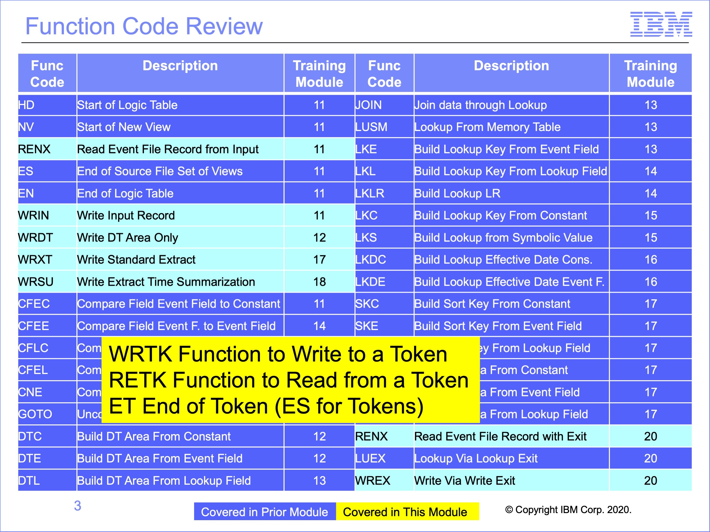
This module covers three special logic table functions, the WRTK which writes a token, the RETK which reads the token and the ET function which signifies the end of a set of token views. These functions are like the WR functions, the RENX function and the ES function for non-token views.
Using SAFR Pipes does not involve special logic table functions.
Slide 4
This module gives an overview of the Pipe and Token features of SAFR.
SAFR views often either read data or pass data to other views, creating chains of processes, each view performing one portion of the overall process transformation
Pipes and Tokens are ways to improve the efficiency with which data is passed from one view to another
Pipes and Tokens are only useful to improve efficiency of SAFR processes; they do not perform any new data functions not available through other SAFR features.
Slide 5
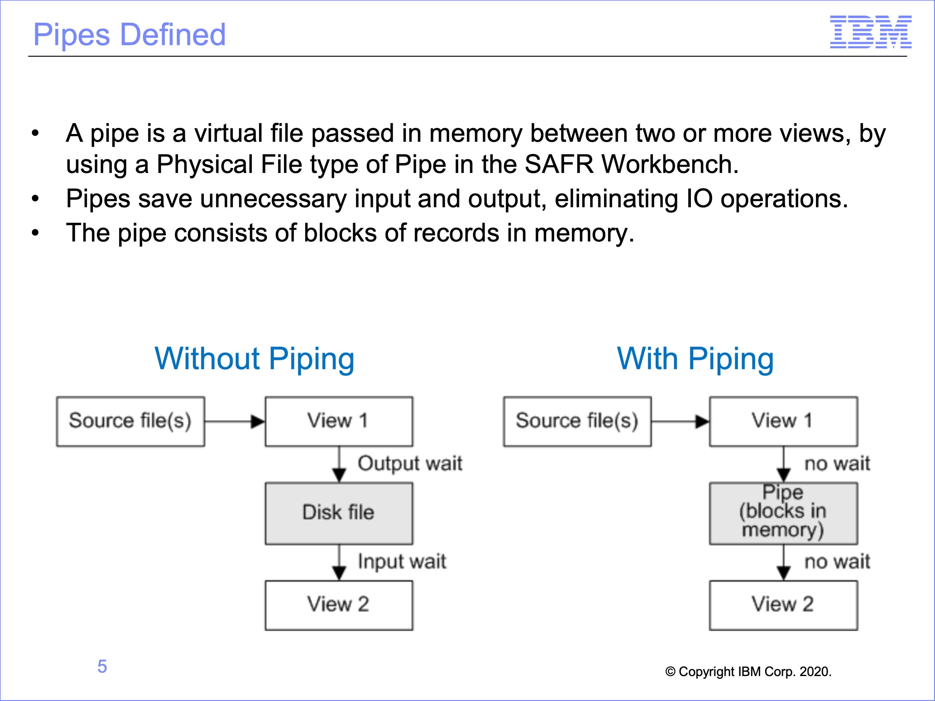
A pipe is a virtual file passed in memory between two or more views. A pipe is defined as a Physical File of type Pipe in the SAFR Workbench.
Pipes save unnecessary input and output. If View 1 outputs a disk file and View 2 reads that file, then time is wasted for output from View 1 and input to View 2. This configuration would typically require two passes of SAFR, one processing view 1 and a second pass processing view 2.
If there is a pipe placed between View 1 and View 2, then the records stay in memory, and no time is wasted and both views are executed in this single pass.
The pipe consists of blocks of records in memory.
Slide 6
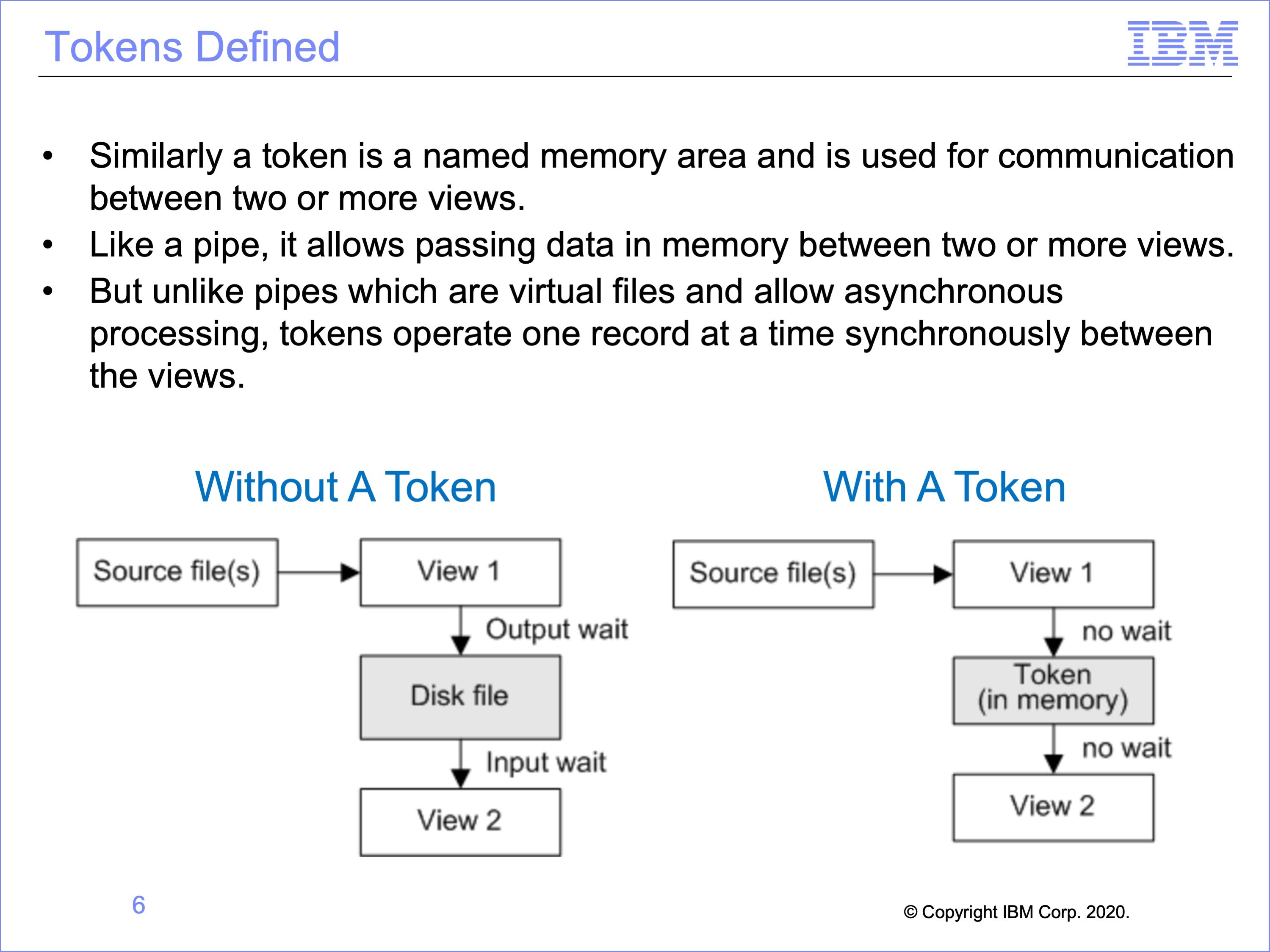
Similarly a token is a named memory area. The name is used for communication between two or more views.
Like a pipe, it allows passing data in memory between two or more views.
But unlike pipes which are virtual files and allow asynchronous processing, tokens operate one record at a time synchronously between the views.
Slide 7
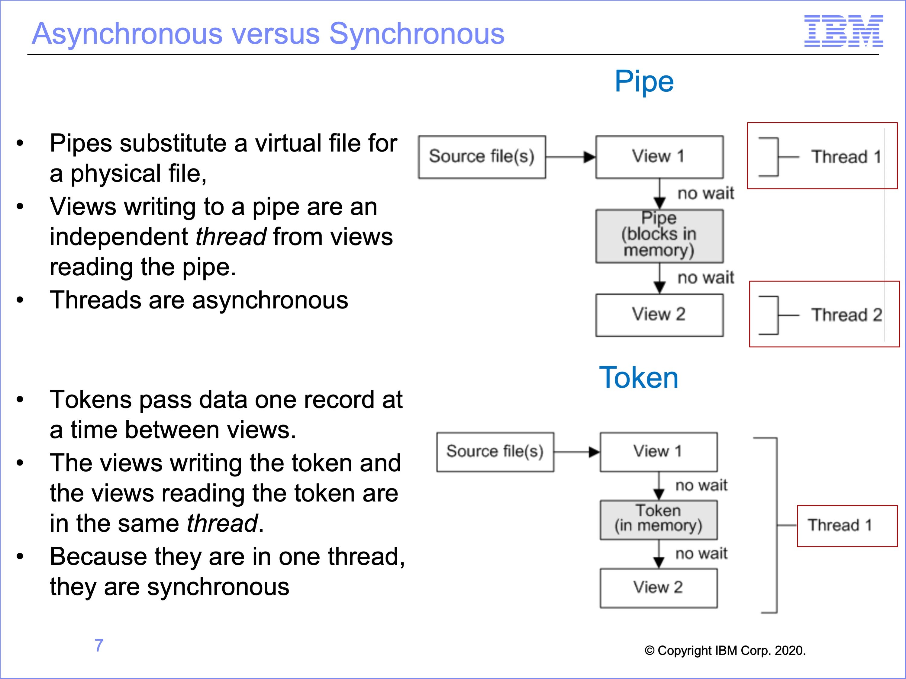
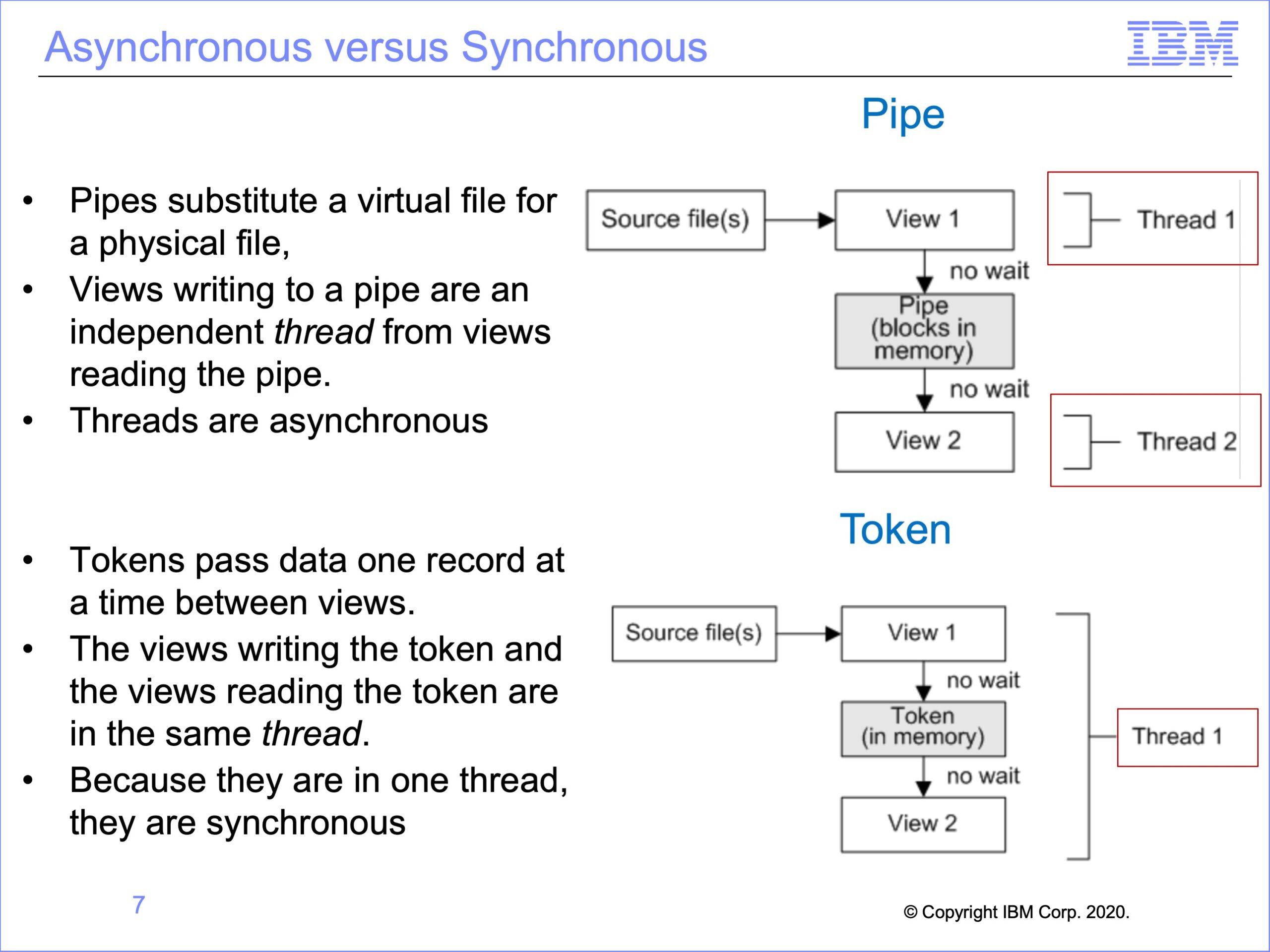
Because Pipes simply substitute a virtual file for a physical file, views writing to a pipe are an independent thread from views reading the pipe.
Thus for pipes both threads are asynchronous
Tokens though pass data one record at a time between views. The views writing the token and the views reading the token are in the same thread.
Thus for tokens there is only one thread, and both views run synchronously
Slide 8
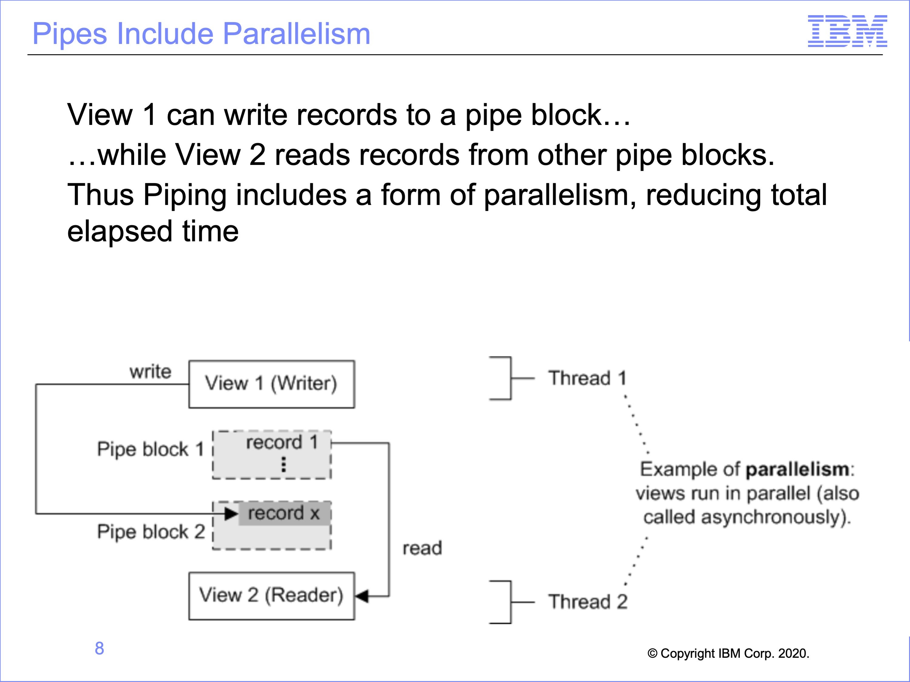
An advantage of pipes is that they include parallelism, which can decrease the elapsed time needed to produce an output. In this example, View 2 runs in parallel to View 1. After View 1 has filled block 1 with records, View 2 can begin reading from block 1. While View 2 is reading from block 1, View 1 is writing new records to block 2. This advantage is one form of parallelism in SAFR which improves performance. Without this, View 2 would have to wait until all of View 1 is complete.
Slide 9
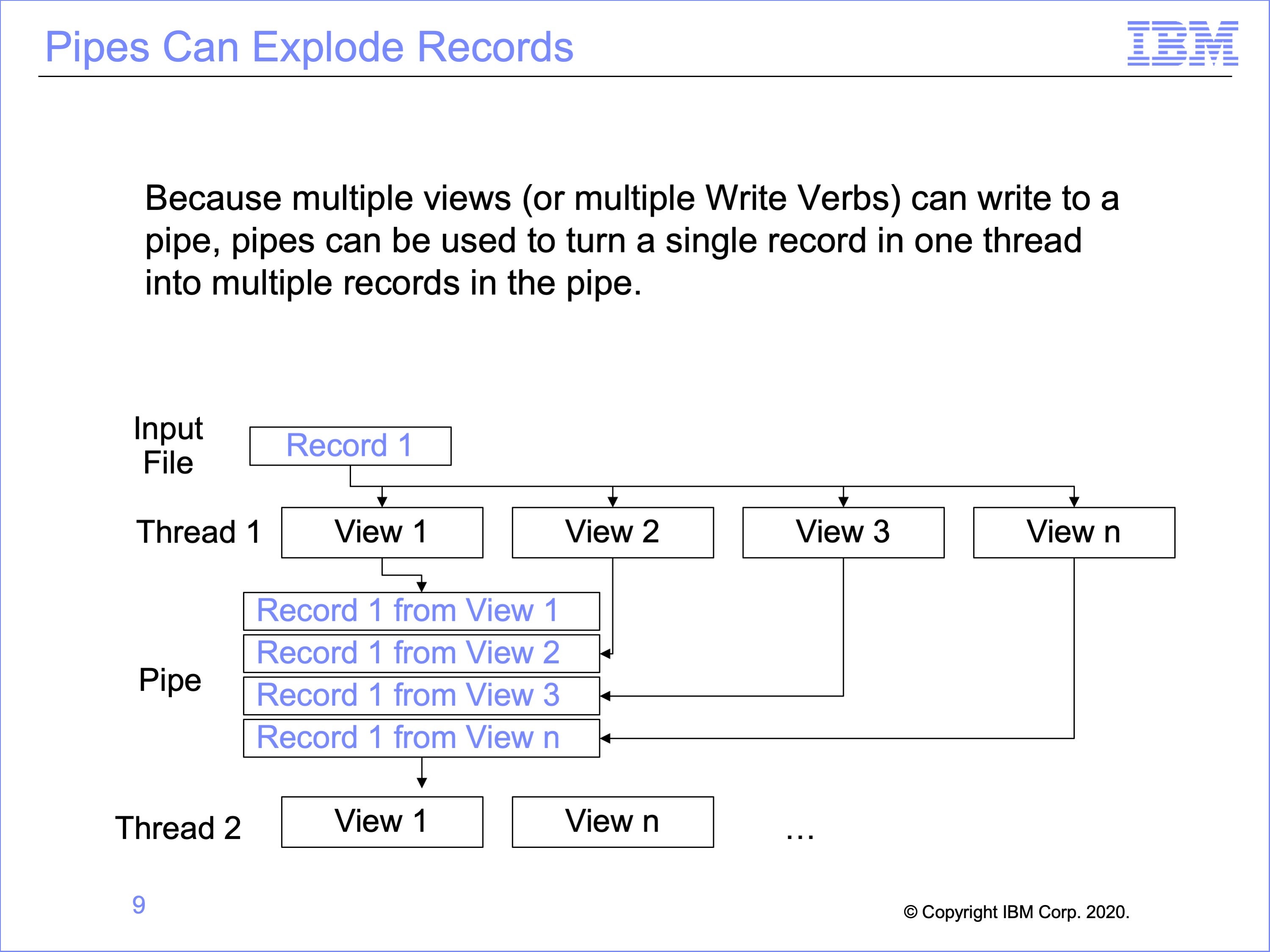
Pipes can be used to multiply input records, creating multiple output records in the piped file, all of which will be read by the views reading the pipe. This can be used to perform an allocation type process, where a value on a record is divided into multiple other records.
In this example, a single record in the input file is written by multiple views into the pipe. Each of these records is then read by the second thread.
Slide 10
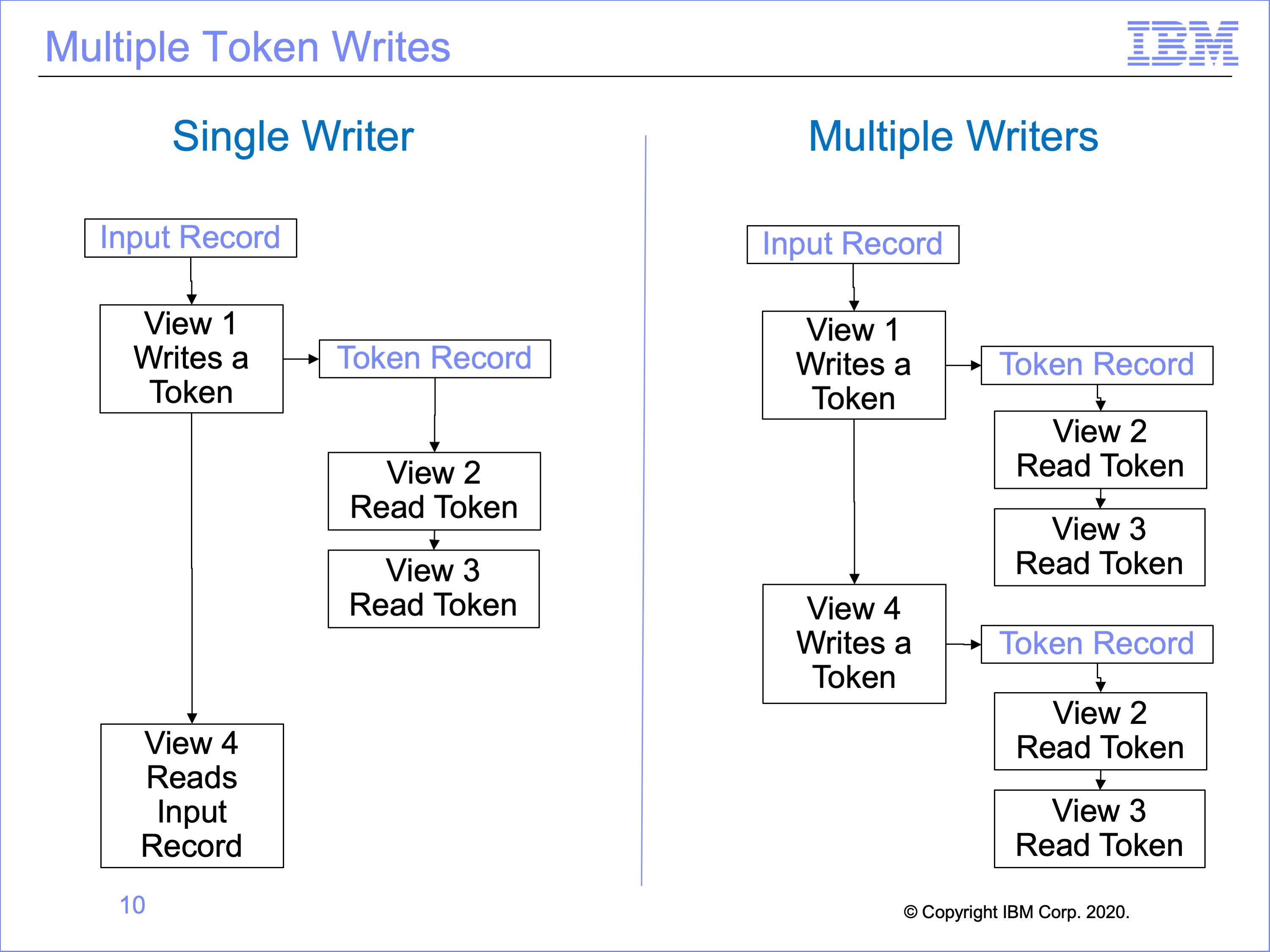
Multiple views can write tokens, but because tokens can only contain one record at a time, token reader views must be executed after each token write. Otherwise the token would be overwritten by a subsequent token write view.
In this example, on the left a single view, View 1, writes a token, and views 2 and 3 read the token. View 4 has nothing to do with the token, reading the original input record like View 1.
On the right, both views 1 and 4 write to the token. After each writes to the token, all views which read the token are called.
In this way, tokens can be used to “explode” input event files, like pipes.
Slide 11
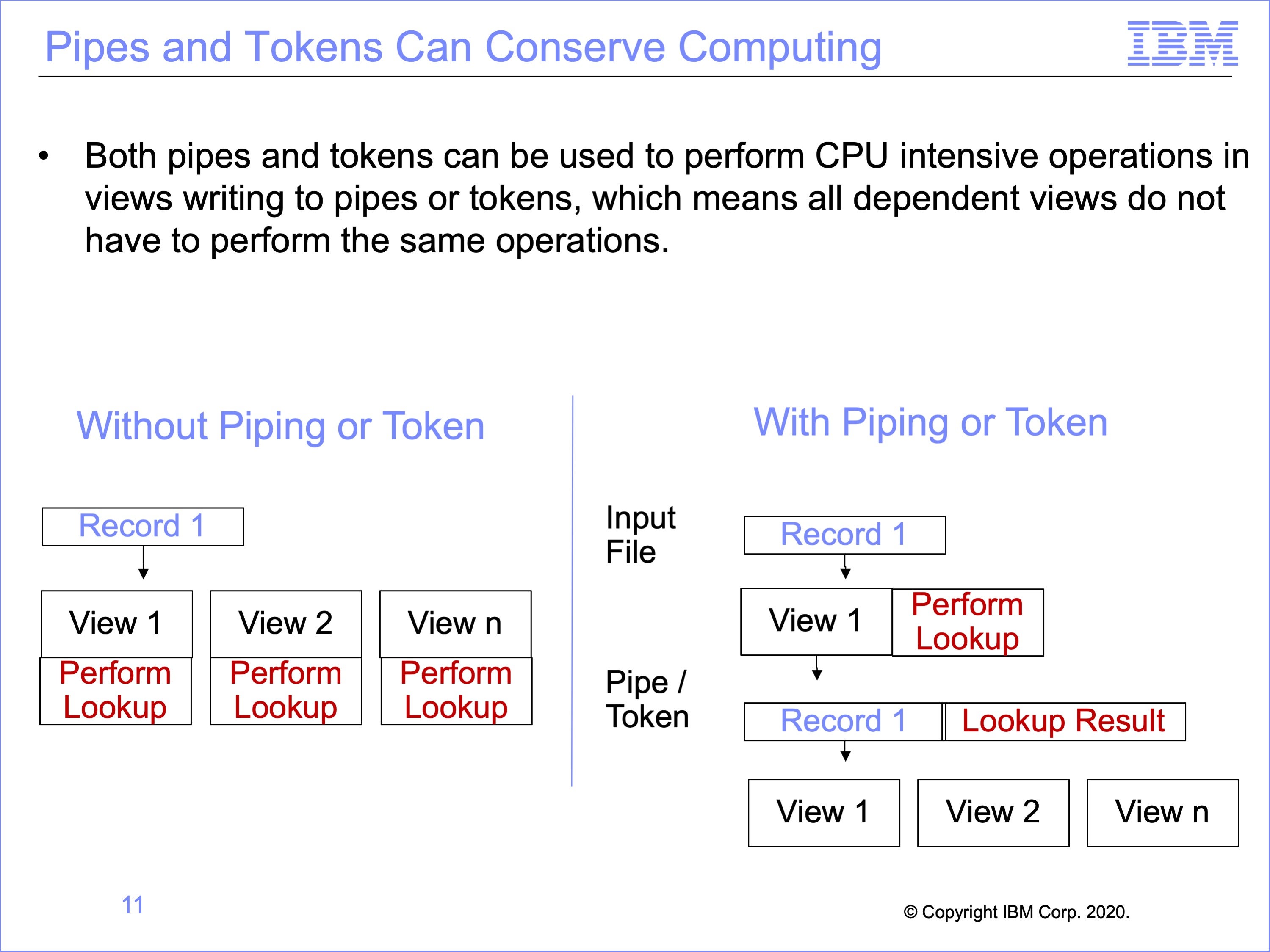
Both pipes and tokens can be used to conserve or concentrate computing capacity. For example CPU intensive operations like look-ups, or lookup exits, can be performed one time in views that write to pipes or tokens, and the results added to the record that is passed onto to dependent views. Thus the dependent, reading views will not have to perform these same functions.
In this example, the diagram on the left shows the same lookup is performed in three different views. Using piping or tokens, the diagram on the right shows how this lookup may be performed once, the result of the lookup stored on the event file record and used by subsequent views, thus reducing the number of lookups performed in total.
Slide 12
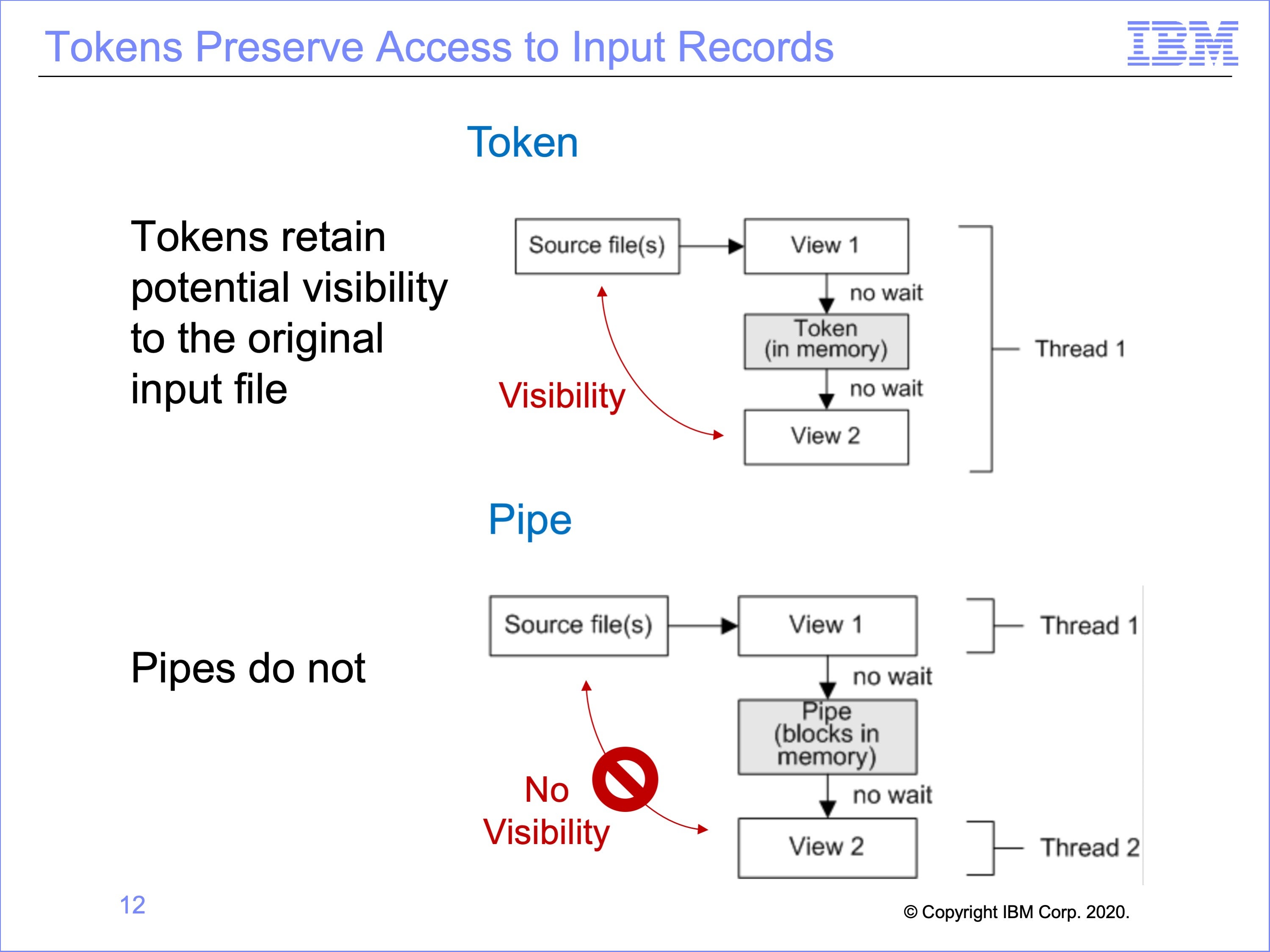
A limitation of pipes is the loss of visibility to the original input record read from disk; the asynchronous execution of thread 1 and thread 2 means the records being processed in thread one is unpredictable.
There are instances where visibility by the view using the output from another view to the input record is important. As will be discussed in a later module, the Common Key Buffering feature can at times allow for use of records related to the input record. Also, the use of exits can be employed to preserve this type of visibility. Token processing, because it is synchronous within the same thread, can provide this capability.
In this example, on the top the token View 2 can still access the original input record from the source file if needed, whereas the Pipe View 2 on the bottom cannot.
Slide 13
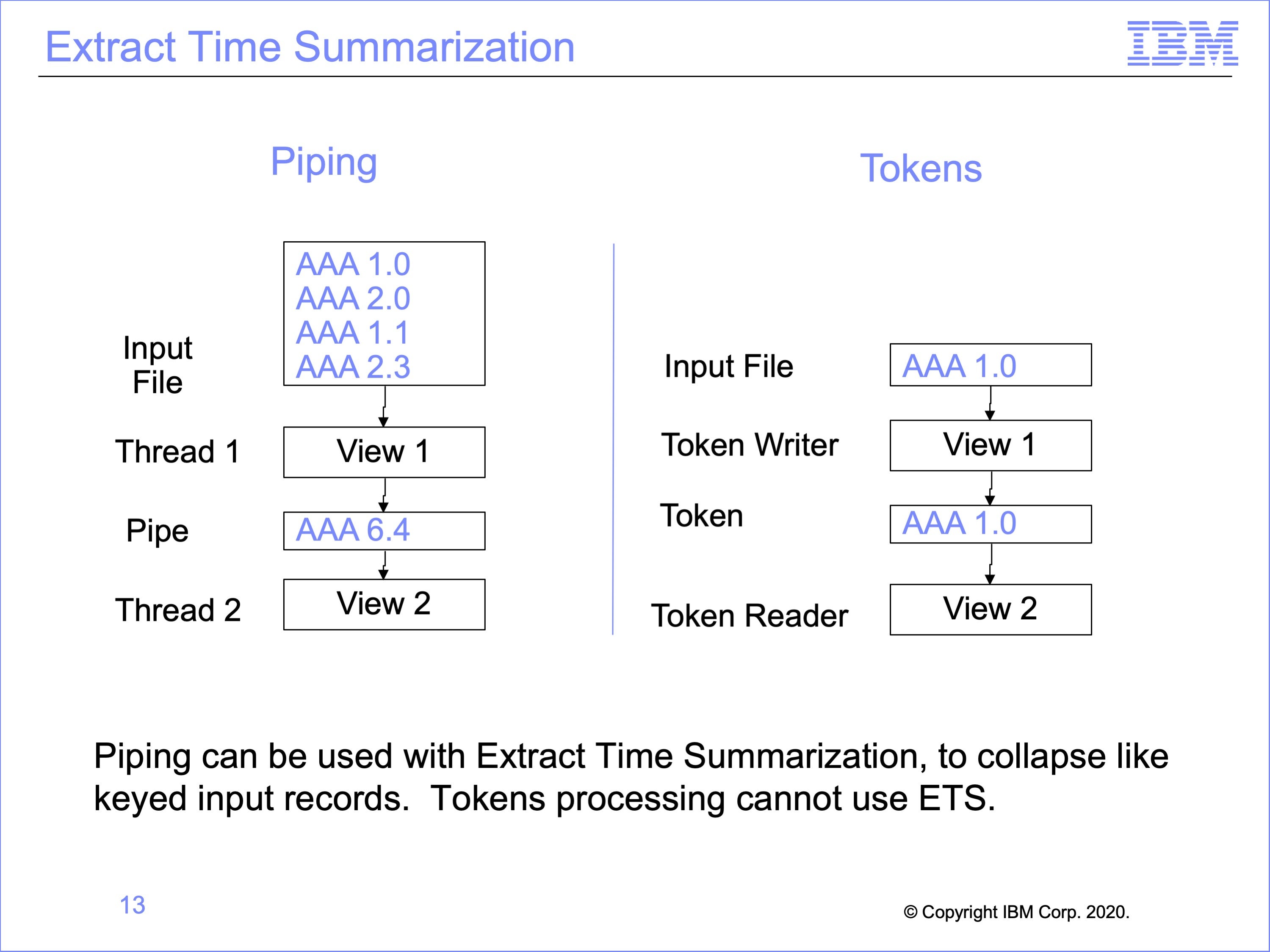
Piping can be used in conjunction with Extract Time Summarization, because the pipe writing views process multiple records before passing the buffer to the pipe reading views. Because tokens process one record at a time, they cannot use extract time summarization. A token can never contain more than one record.
In the example on the left, View 1, using Extract Time Summarization, collapses four records with like sort keys from the input file before writing this single record to the Pipe Buffer. Whereas Token processing on the right will pass each individual input record to all Token Reading views.
Note that to use Extract Time Summarization with Piping, the pipe reading views must process Standard Extract Format records, rather than data written by a WRDT function; summarization only occurs in CT columns, which are only contained in Standard Extract Format Records.
Slide 14
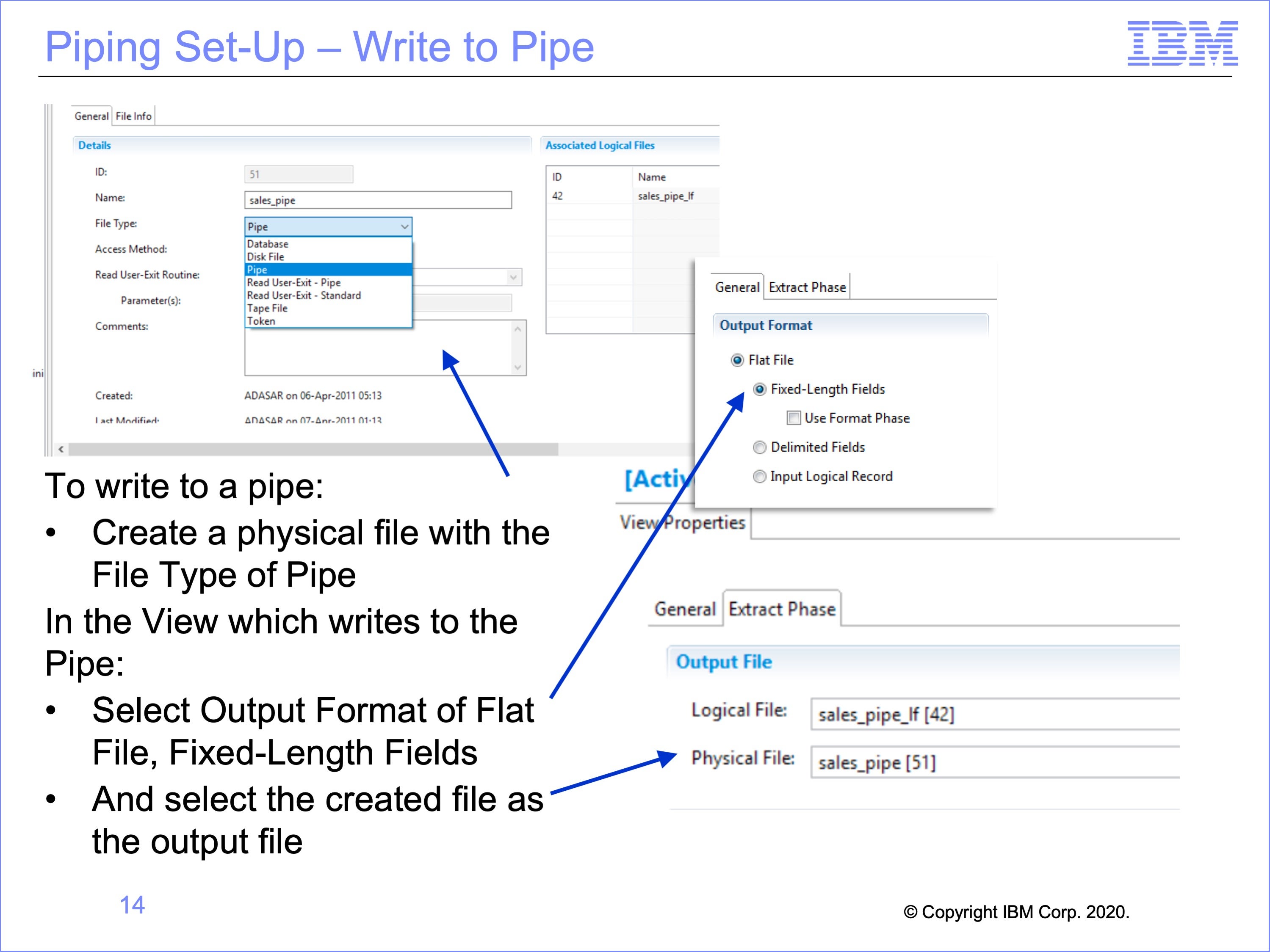
Workbench set-up for writing to, and reading from a pipe is relatively simple. It begins with creating a pipe physical file and a view which will write to the pipe.
Begin by creating a physical file with a File Type of “Pipe”.
Create a view to write to the Pipe, and within the View Properties:
- Select the Output Format of Flat File, Fixed-Length Fields,
- Then select the created physical file as the output file
Slide 15
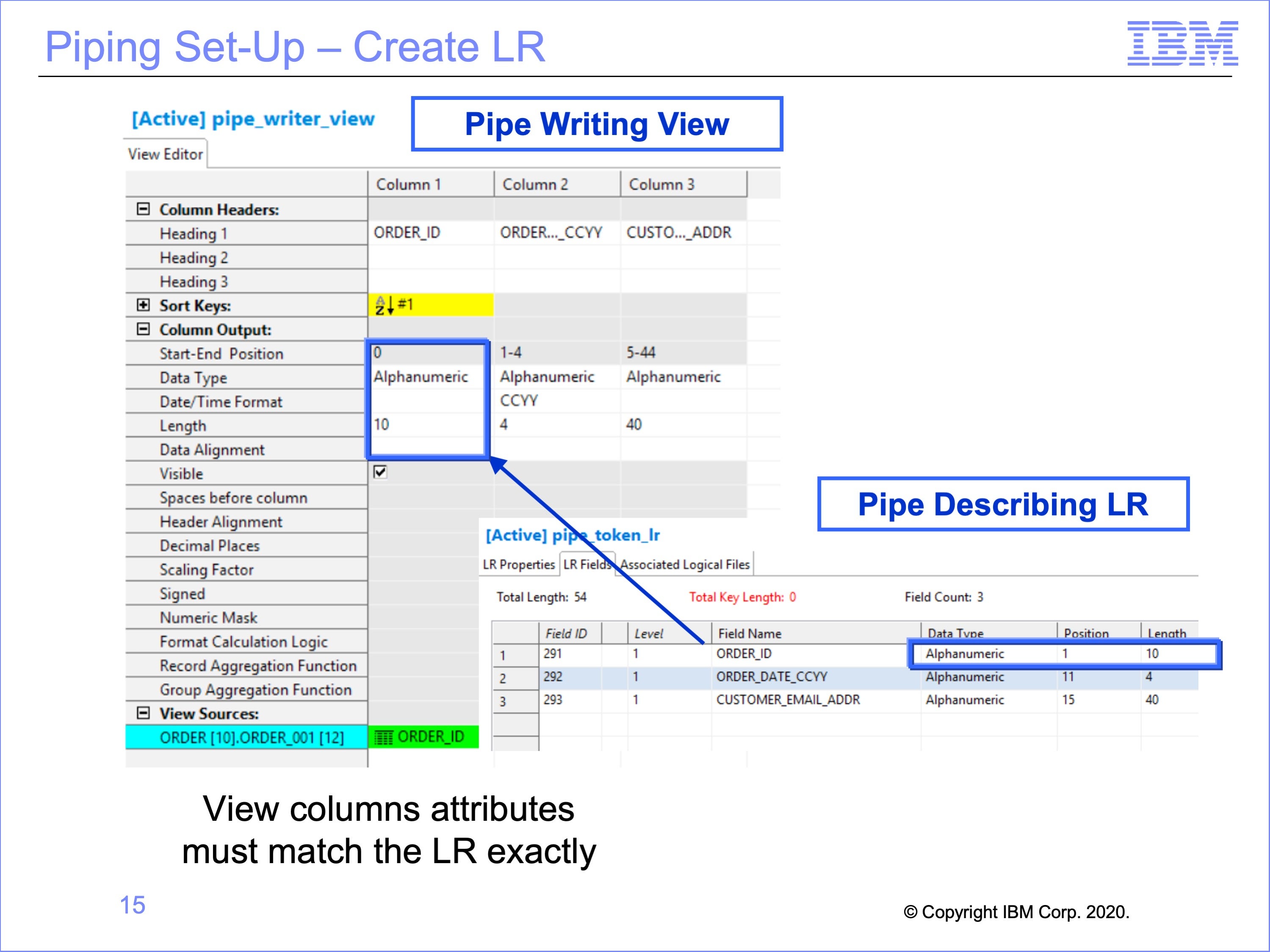
The next step is to create the LR for the Pipe Reader Views to use.
The LR used for views which read from the pipe must match exactly the column outputs of the View or Views which will write to the Pipe. This includes data formats, positions, lengths and contents.
In this example, Column 1 of the View, ”Order ID” is a 10 byte field, and begins at position 1. In the Logical Record this value will be found in the Order_ID field, beginning at position 1 for 10 bytes.
Preliminary testing of the new Logical Record is suggested, making the view write to a physical file first, inspect the view output, and ensure the data matches the Pipe Logical Record, and then change the view to actually write to a pipe. Looking at an actual output file to examine positions is easier than using the trace to detect if positions are correct as the Pipe only shows data referenced by a view, not the entire written record produced by the pipe writing view.
Slide 16
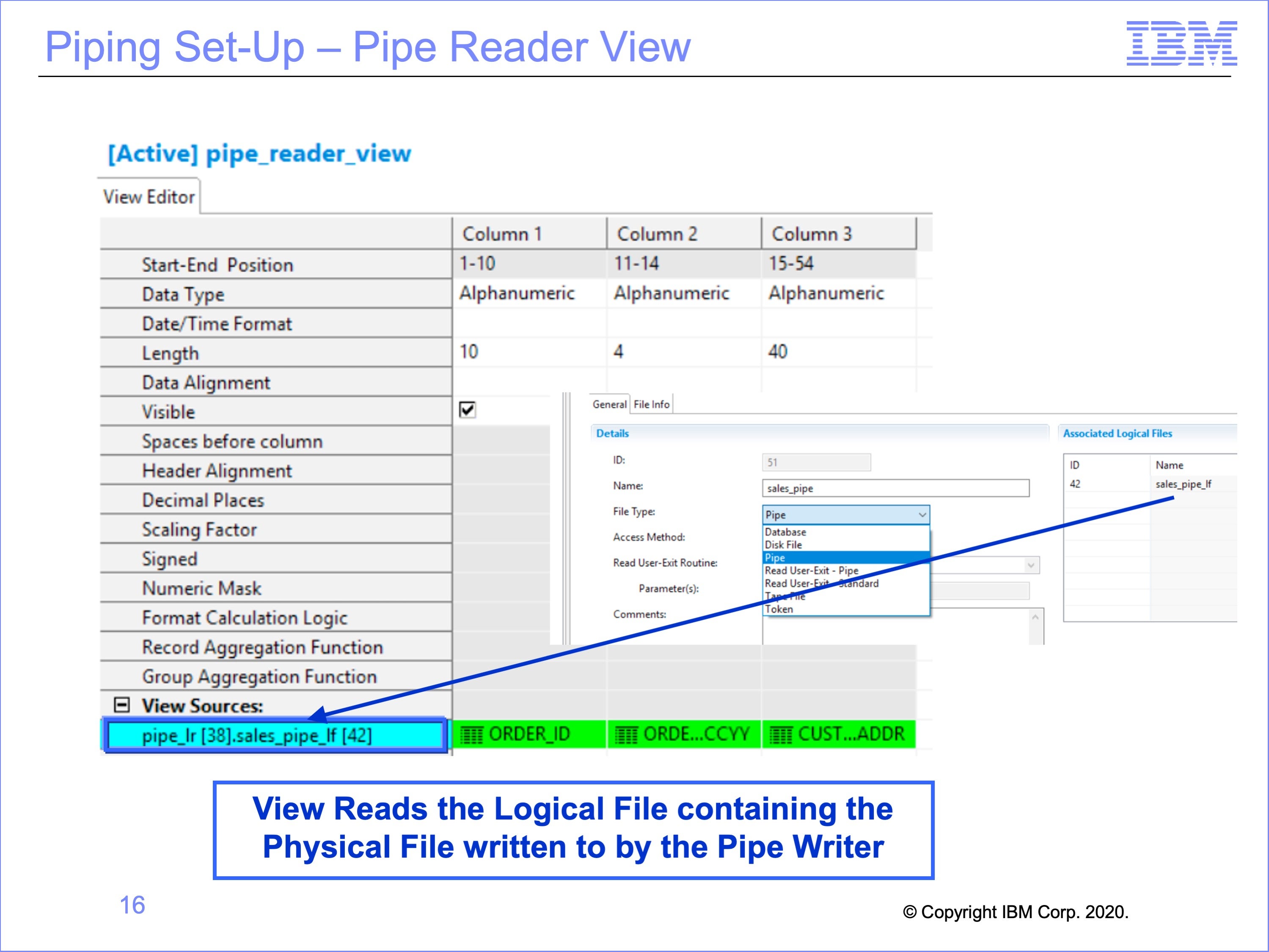
The view which reads the Pipe uses the Pipe Logical Record. It also must read from a Logical File which contains the Pipe Physical File written to by the pipe writer view.
In this example, the view read the pipe-LR ID 38, and the Pipe LF ID 42 Logical File which contains the Physical File of a type Pipe written to by the pipe writing view. The view itself uses all three of the fields on the Pipe Logical Record.
Slide 17
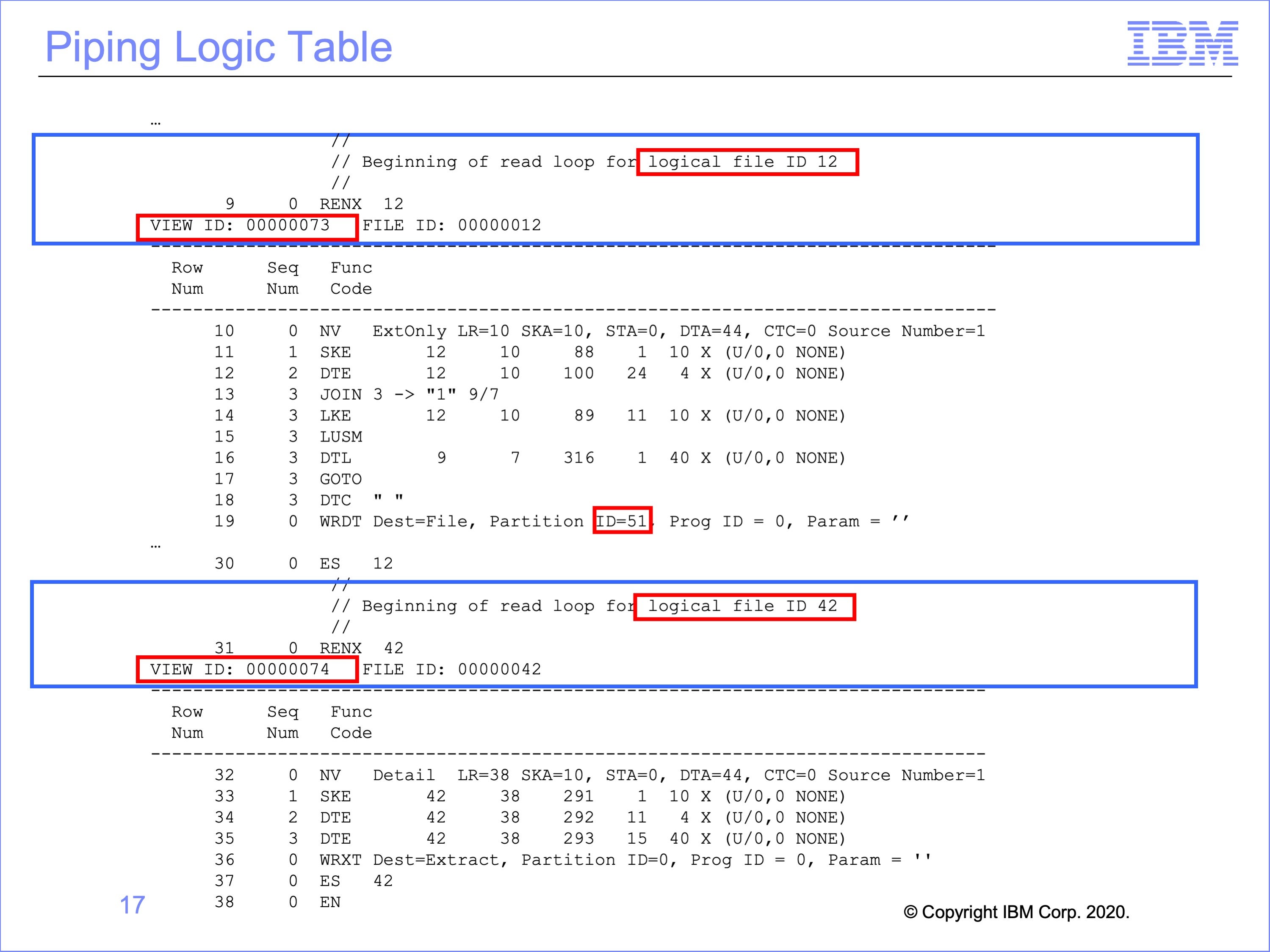
This is the logic table generated for the piping views. The pipe logic table contains no special logic table functions. The only connection between the ES sets is the shared physical file entity.
The first RENX – ES set is reading Logical File 12. This input event file is on disk. The pipe writing view, view number 73, writes extracted records to Physical File Partition 51.
The next RENX – ES set reads Logical File 42. This Logical File contains the same Physical File partition (51) written to by the prior view. The Pipe Reader view is view 74.
Slide 18
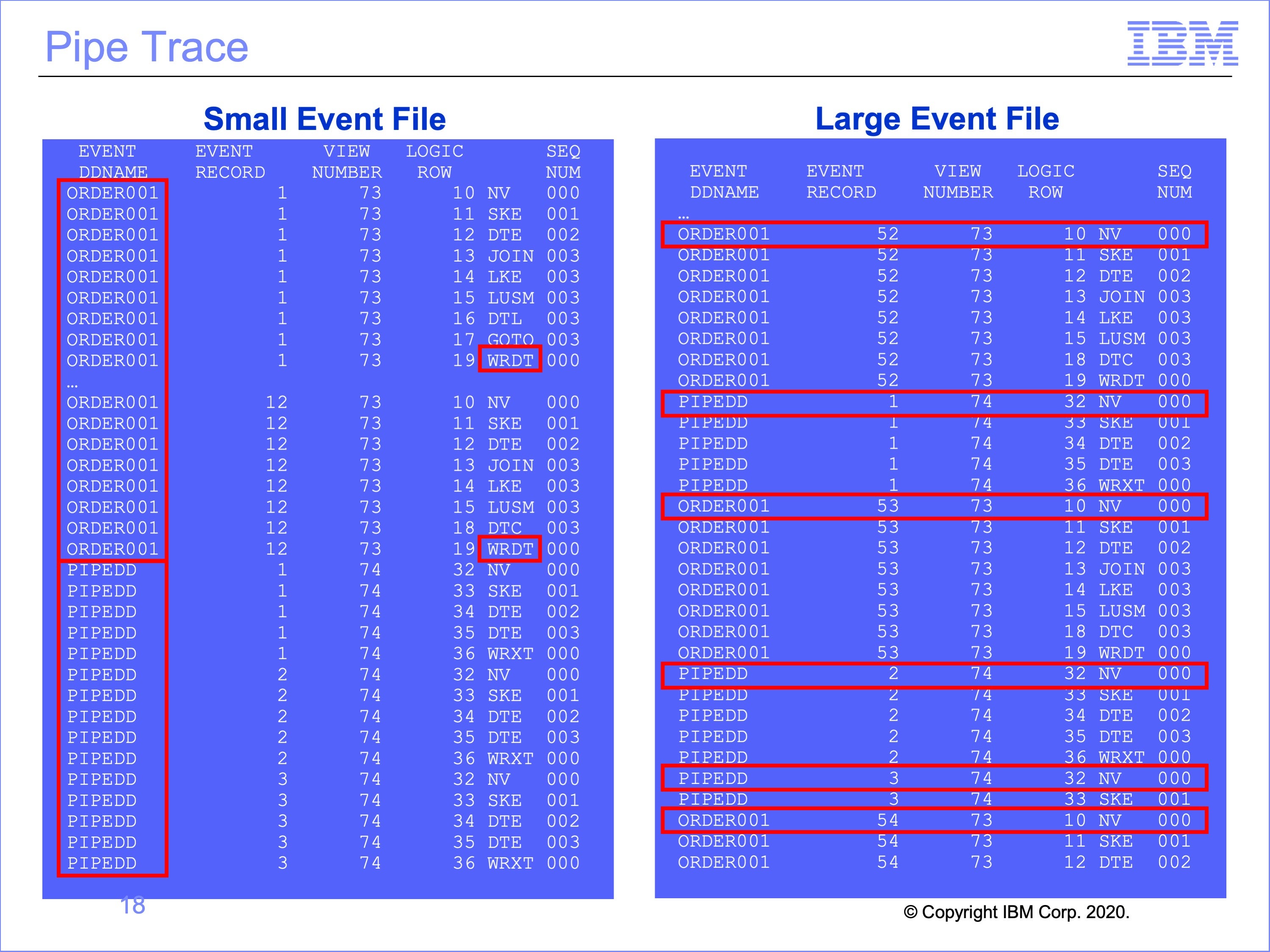
This the the trace for piped views. In the example on the left, the thread reading the event file, with a DD Name of ORDER001, begins processing input event records. Because the pipe writer view, number 73, has no selection criteria, each record is written to the Pipe by the WRDT function. All 12 records in this small input file are written to the Pipe.
When all 12 records have been processed, Thread 1 has reached the end of the input event file, it stops processing, and turns the pipe buffer over to Thread 2 for processing.
Thread 2, the Pipe Reader thread, then begins processing these 12 records. All 12 records are processed by the pipe reader view, view number 74.
As shown on the right, if the input event file had contained more records, enough to fill multiple pipe buffers, the trace still begins with Thread 1 processing, but after the first buffer is filled, Thread 2, the pipe reading view, begins processing. From this point, the printed trace rows for Thread 1 and Thread 2 may be interspersed as both threads process records in parallel against differing pipe buffers. This randomness is highlighted by each NV function against a new event file record
Slide 19
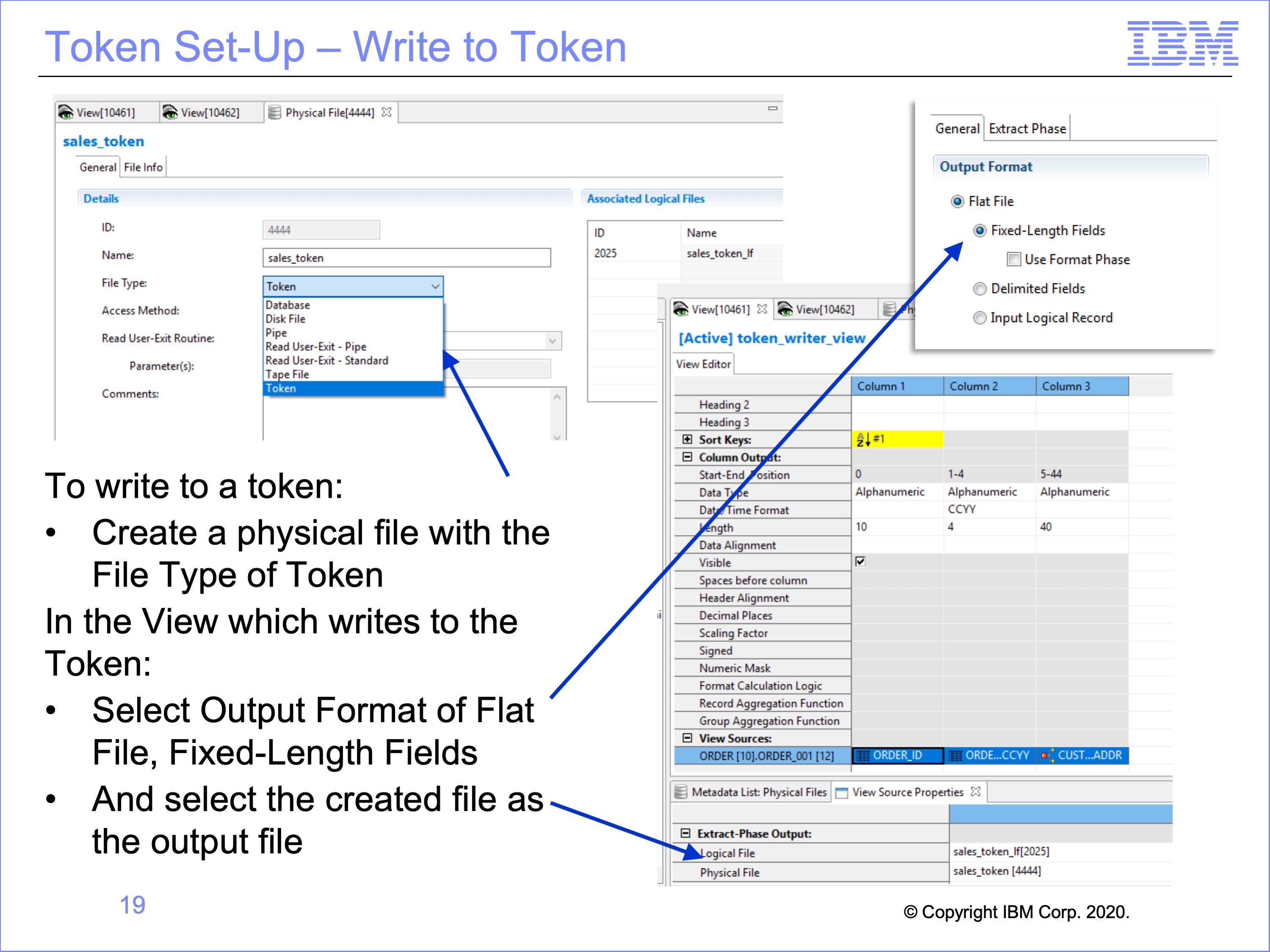
Workbench set-up for writing to, and reading from a token is very similar to the set-up for pipes. It begins with creating a physical file with a type of token, and a view which will write to the token.
Begin by creating a physical file with a File Type of “Token”.
Create a view to write to the token, and within the View Properties, select the Output Format of Flat File, Fixed-Length Fields.
Then in the proprieties for the Logical Record and Logical File to be read, select the output Logical File and created Physical File as the destination for the view
Slide 20
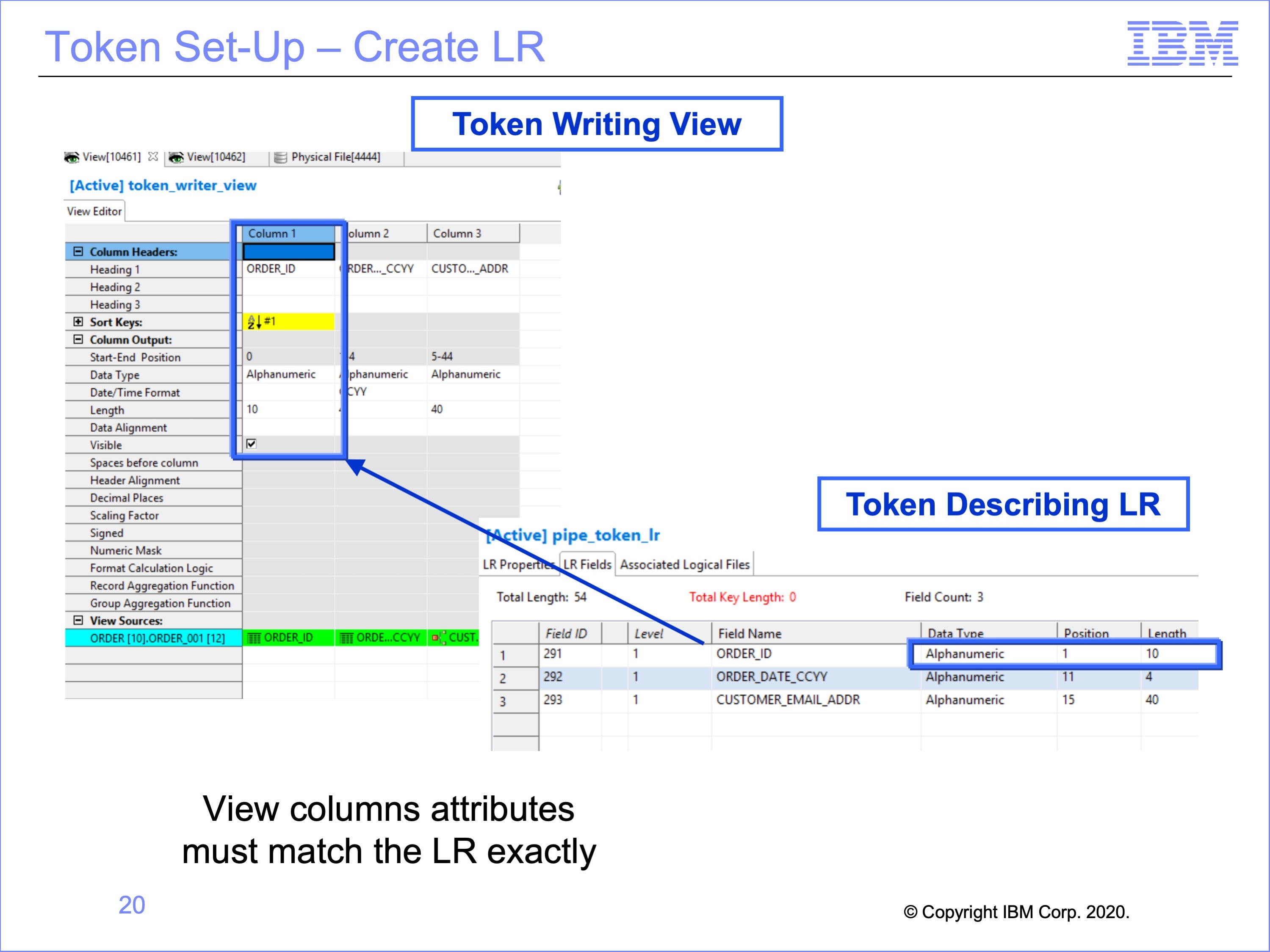
Like pipe usage, the next step is to create the Logical Record for the Token Reader Views to use. In our example, we have reused the same Logical Record used in the piping example. Again, the logical record which describes the token must match the output from the view exactly, including data formats, positions, lengths and contents.
Slide 21
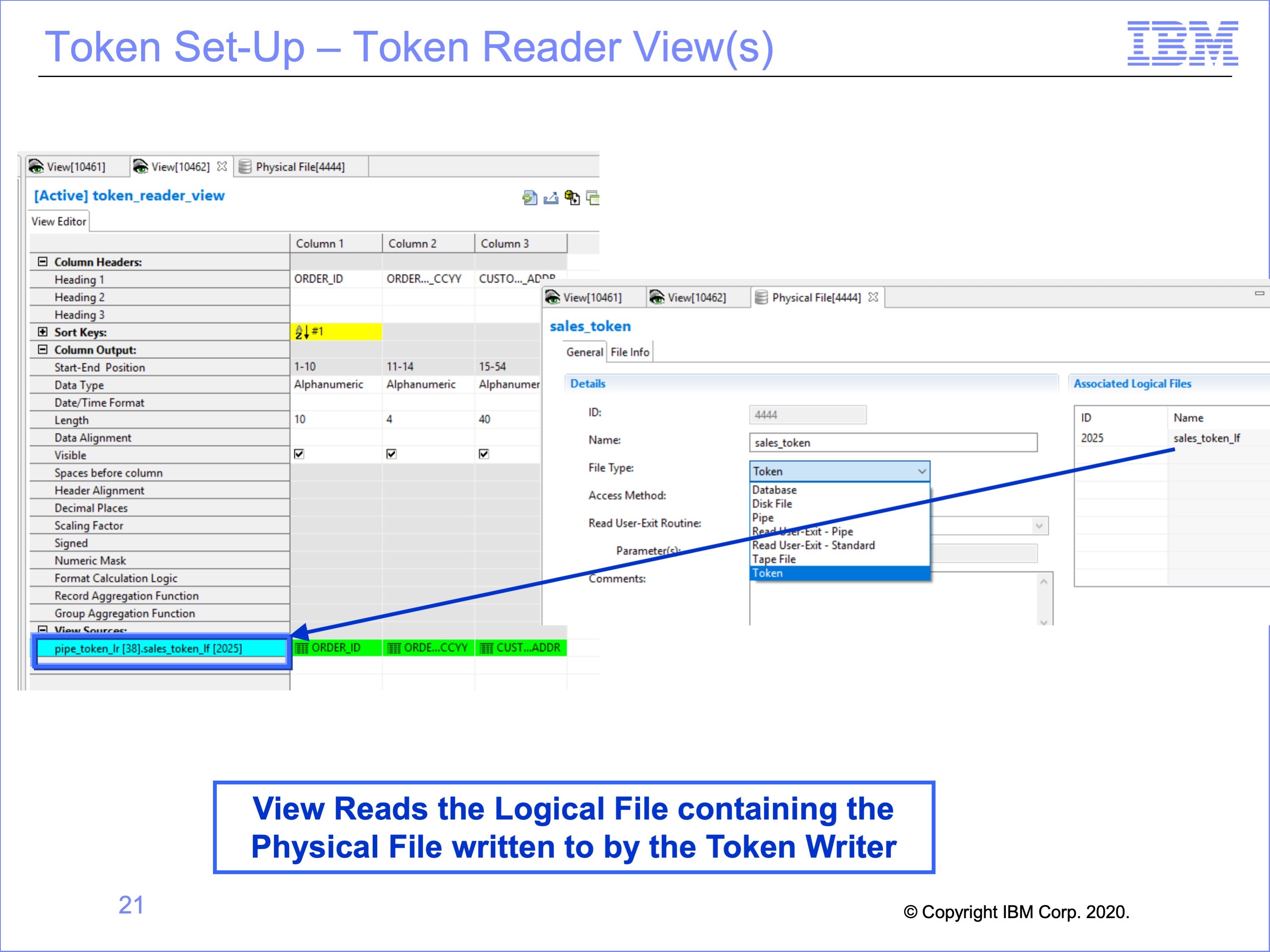
Again, the view which reads the Token uses this new Logical Record. It also must read from a Logical File which contains the Token Physical File written to by the token writer view.
Note that the same Logical File must be used for both the token writer and token reader; using the same Physical File contained in two different Logical Files causes an error in processing.
Slide 22
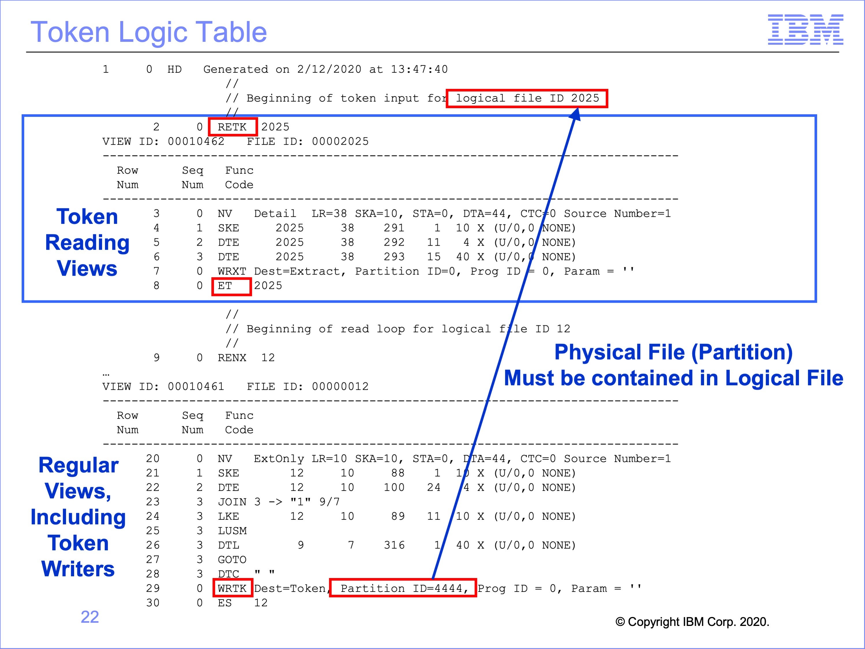
This is the logic table generated for the token views.
Any views which read a token are contained within an RETK – Read Next Token / ET – End of Token set at the top of the logic table.
The token writer view or views are listed below this set in the typical threads according to the files they read; the only change in these views is the WRTK logic table function, which Writes a Token shown at the bottom of the logic table in red.
Although the token reading views are listed at the top of the Logic Table, they are not executed first in the flow. Rather, the regular threads process, and when they reach an WRTK Write Token logic table function, the views in the RETK thread are called and processed. Thus the RETK – ET set is like a subroutine, executed at the end of the regular thread processing.
In this example, view 10462 is reading the token written by view 10461. View 10462 is contained within the RETK – ET set at the top of the logic table. View 10461 has a WRTK function to write the token. After execution of this WRTK function, all views in the RETK – ET set are executed.
Slide 23
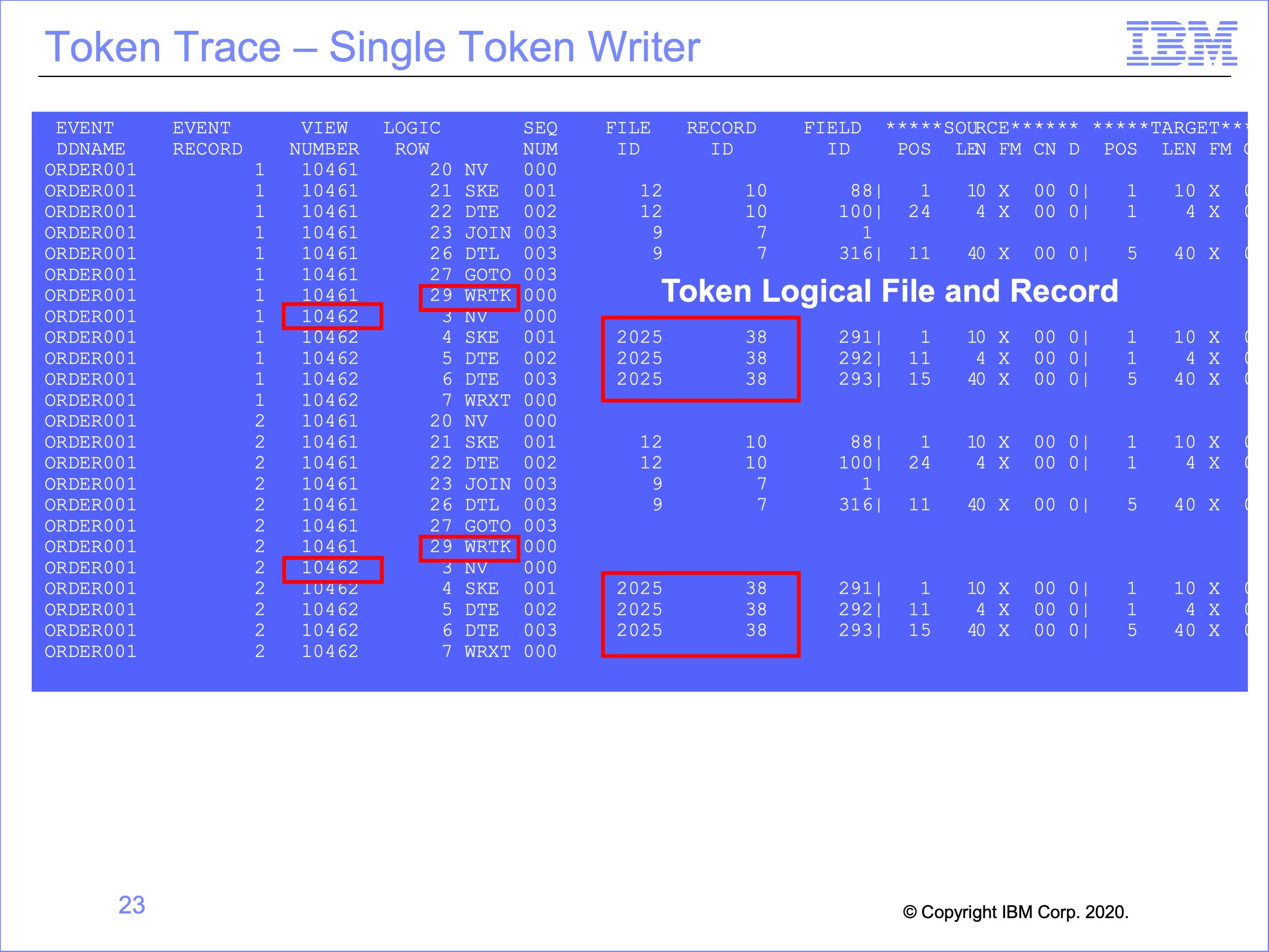
This is the Logic Table Trace for the Token Views.
Note that, unlike the Pipe Example which has multiple Event File DD Names within the Trace, because Tokens execute in one thread, the Event File DD Name is the same throughout, ORDER001 in this example.
The WRTK Write Token Function, on view 10461 in this example, which ends the standard thread processes are immediately followed by the Token Reading view or views, view 10462 in this example. The only thing that makes these views look different from the views reading the input event file is that they are processing against a different Logical File and Logical Record, Logical File ID 2025 and Logical Record ID 38 in this example.
Slide 24
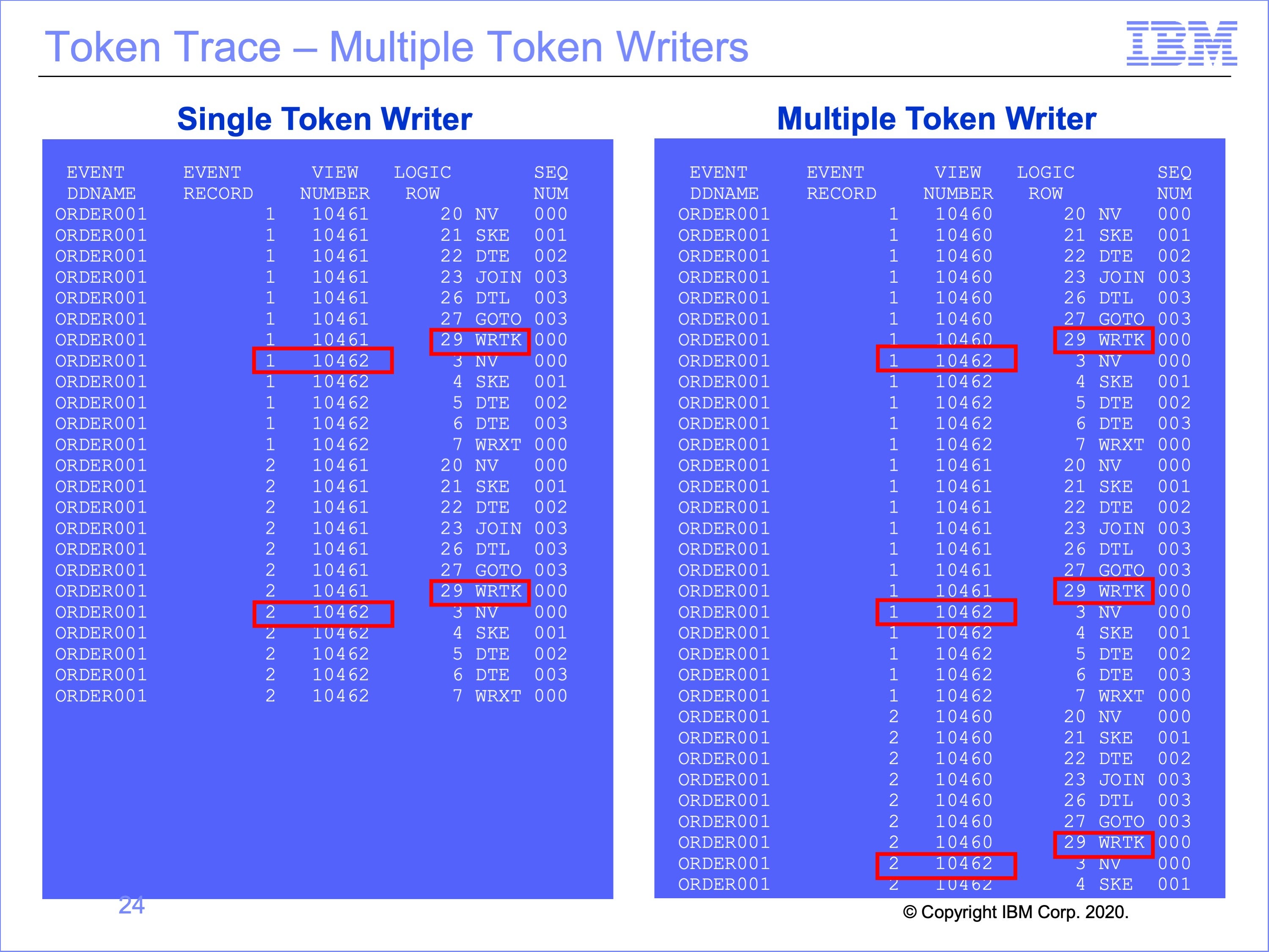
The trace on the right has been modified to show the effect of having multiple token writing views executing at the same time.
Note multiple executions of View 10462, the token reading view processing the same Event Record1, from the Same Event DD Name ORDER001, after each token writing views, 10460 and 10461.
Slide 25
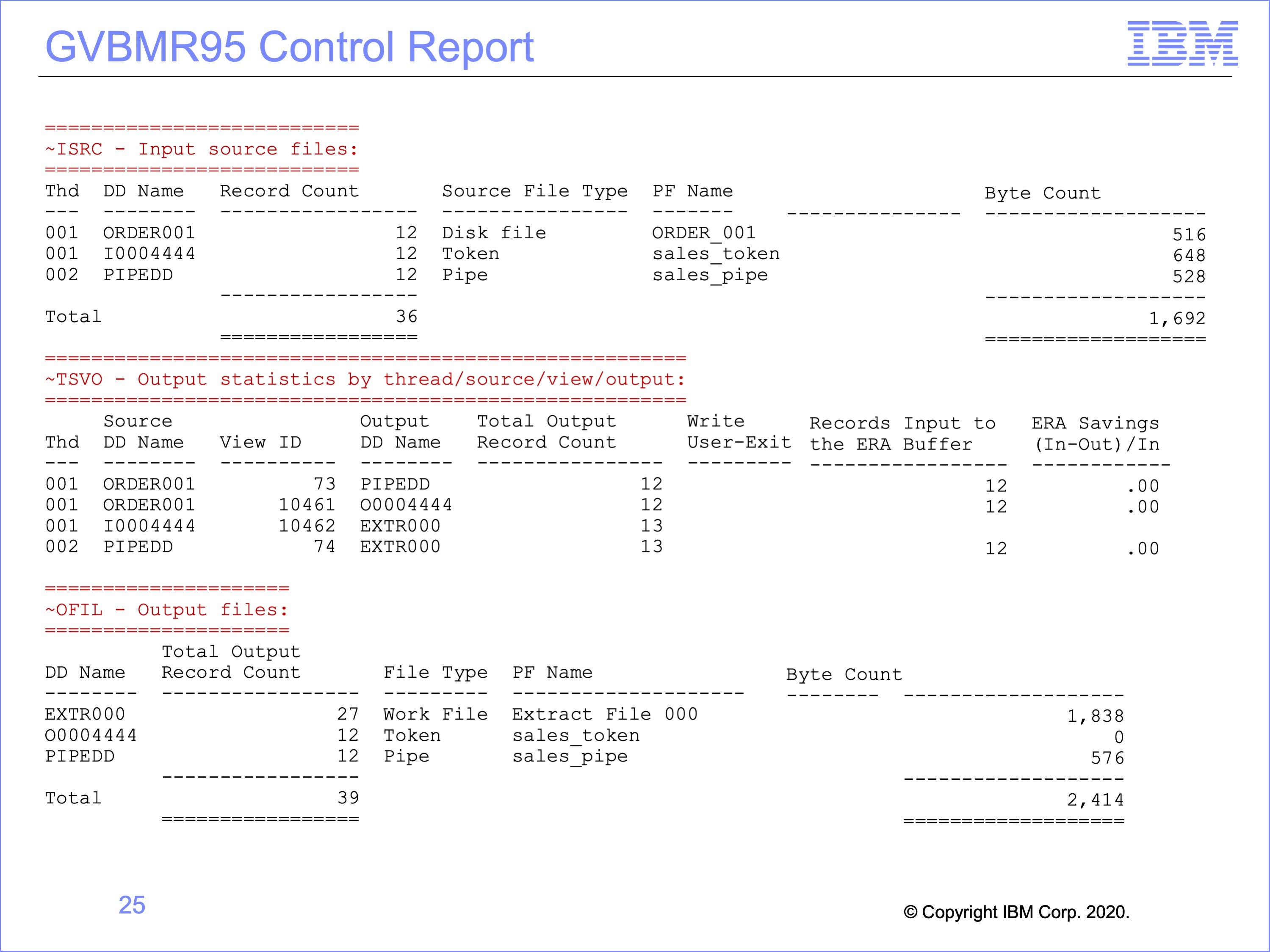
The GVBMR95 control report shows the execution results from running both the Pipe and Token views at the same time.
- At the top of the report, the Input files listed include the
- Disk File, the event file for both the pipe and token writing views
- the Token (for the Token Reading views), and
- the Pipe (for the Pipe Reading views)
- The bottom of the report shows the final output disposition, showing records were written to
- an Extract File (shared by the pipe and token reading views),
- the Token (for the Token Writing View) and
- the Pipe (for the Pipe Writing View)
- The center section shows more details about each one of the Views.
Slide 26
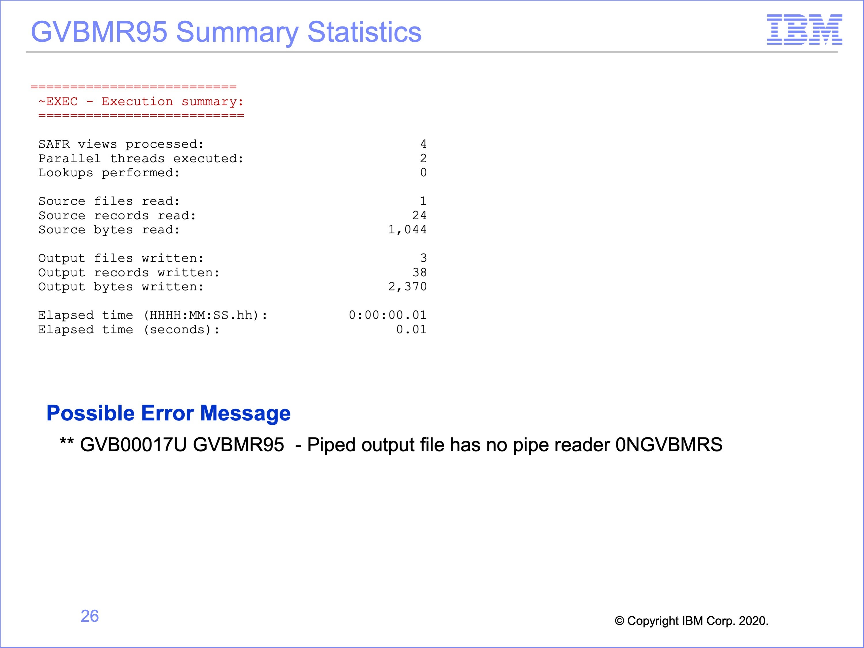
The top of this slide shows the final run statistics about the run from the GVBMR95 control report.
Note that a common error message may be encountered if view selection for the pass is not carefully constructed, for either Pipes or Tokens. Execution of a pass which contains only Pipe Writers and no Pipe Readers will result in this message. The opposite is also true, with no Pipe Writers and only Pipe Readers selected. The same is also true for token processes. Pairs of views must be executed for either process, matched by Logical Files containing matching Physical Files for the process to execute correctly.
Slide 27
This module described using piping and tokens. Now that you have completed this module, you should be able to:
- Describe uses for the SAFR piping feature
- Read a Logic Table and Trace with piping
- Describe uses for the SAFR token feature
- Read a Logic Table and Trace with tokens
- Debug piping and token views
Slide 28
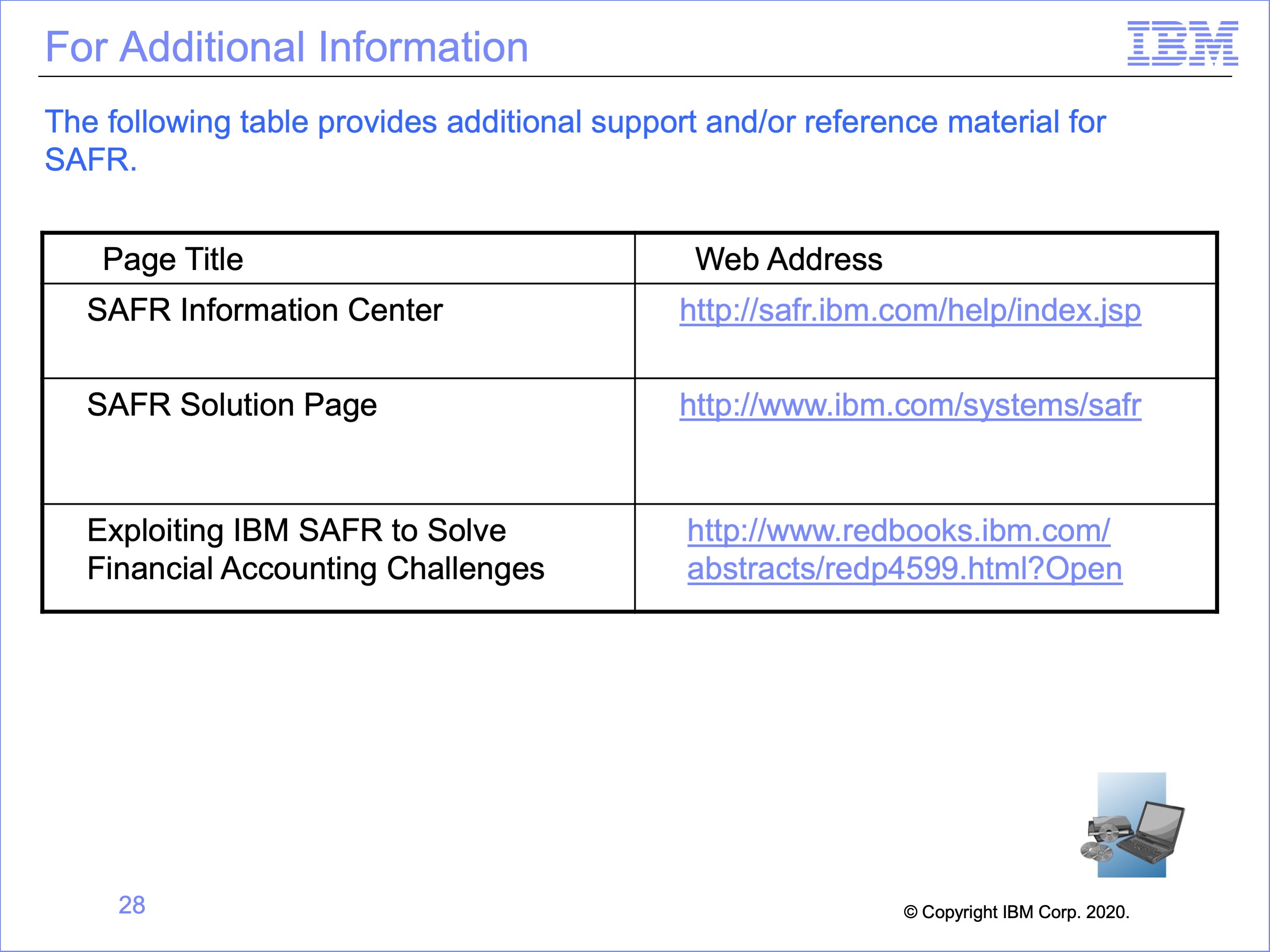
Additional information about SAFR is available at the web addresses shown here. This concludes Module 22, The SAFR Piping and Token Functions
Slide 29