The slides for the following video are shown below:
Slide 1

Welcome to the training course on IBM Scalable Architecture for Financial Reporting, or SAFR. This is Module 17, Format Phase Views
Slide 2

Upon completion of this module, you should be able to:
- Describe uses for Format-Phase Views
- Read a Logic Table and Trace with format-phase views
- Explain the Function Codes used in the example
- Debug format-phase views
Slide 3

The prior modules covered the function codes highlighted in blue. Those to be covered in this module are highlighted in yellow.
Slide 4

The Format Phase is the final possible phase of the Performance Engine Processes. Views that require only extraction and no sorting or aggregation are completed at the Extract Phase.
Any view that requires the following must continue to the Format Phase:
- Summarize records
- Use output record filtering which is applied after records are subtotaled
- Produce sorted outputs
- Create delimited files, and
- Make hardcopy formatted printed reports
The Format Phase is run after the Extract Phase (GVBMR95) has completed extracting all data.
Slide 5

The GVBMR95 Extract Engine performs functions one event or transaction record at a time. Records are evaluated for inclusion or exclusion in output files, fields are extracted and used to build keys for joins, all one record at a time. Except for Extract Time Summarization (which will be discussed in a later module), GVBMR95 does not produced summarized results.
You may remember that in Module 10 we discussed summary reports. These report aggregate detailed records to produce summarized results. Even detailed reports can include subtotals, which are the results of summarizing many detailed records. To perform these function, the Format Phase Engine, GVBMR88 is required.
Slide 6

Extracted data is passed in a special format, called the SAFR Standard Extract File, from the Extract Phase to the Format Phase. Creating this format requires unique Logic Table Functions in the Extract Phase. In this module we will focus on these Format Phase logic table functions and introduce the Extract File Format.
Slide 7

The Extract Engine, GVBMR95 is a parallel processing engine, yet the Format Phase, GVBMR88 is not; it processes only one Extract Work File. Yet that extract file can contain the extracted records for multiple views. Each GVBMR88 execution can produce multiple extract files. The final output for each view is produced by only one format engine execution.
In this example the extract file on the left has the extracted records for views 2, 3 and 4, while the one on the right has the records for views 8, 9 and 10. The GVBMR88 execution on the left produces the output for view 2, 3 and 4, while the one on the right produces the output for view 8, 9 and 10.
Slide 8

As previously mentioned, GVBMR95 creates a specially formatted extract file and there can be one or more created based on how the data needs to be processed. The extract file to be used by each view is assigned in the view parameters screen, the Extract Phase Tab. The Extract Engine concatenates the assigned number to the value “EXTR” with three digits representing the Extract Work File Number, beginning with zeros if necessary to form the DD Name to be used. It also concatenates this number with the value “SORT” to write the parameters specifying how the views should be sorted.
This example uses Extract Work File Number 1. The extract records will then be written to the file assigned to the DD Name EXTR001, and the sort parameters to SORT001. These two files must be passed via the JCL as SORTIN and SYSIN files respectively to the Format Engine GVBMR88.
Slide 9

The Format Phase Extract record has a standard format for all views. This specialized format allows for very efficient processing of Format Phase views. The Extract and Format engines have clearly defined functions, such that steps are not repeated between the two engines. The extract file format prepares the data to be sorted and summarized.
The record contains the following segments:
- The control area contains values that describe the rest of the record, like the number of SAFR view columns on this record, and the length of the sort key. The last field in the control area is the view number.
- The Sort Key or SK area contains the values the user has specified the output file should be sorted and/or grouped by.
- The Data Transform or DT area contains alphabetic and alphanumeric and numeric column data that is not used in a format time calculation, including sub-totaling, or format time selection logic.
- The Calculated Transform or CT area contains column data that is either used in a format time calculation, including sub-totaling, or format time selection logic.
The sample data is shown in HEX mode. The first row is the display format, and the next two lines show a half a byte each, first (top line) and last (bottom line). This shows packed and non-printable characters.
Slide 10

In this module, we will use the view shown here as the example view. This view includes a simply lookup for record level filtering. Record level filtering does not affect the format of the extracted records.
This view has 7 columns. The first three columns are sort keys, highlighted by the yellow sort key indicator. In other words the view output will be sorted by the values in these three columns. The records will be sorted first by the Format value in column 1, then the Store ID value in column 2, and finally by the Gender Code in column 3. We know this because of the #1, #2, and #3 showing the sort key position.
Slide 11

Columns 4 and 5 contain data that requires a calculation. In this case, they are to be summed, to produce the total for a change in the sort key value. Thus the data required for these calculations will be placed in the Calculated Transform or CT area of the extract record.
Slide 12

Columns 6 and 7 are date fields which are not used in a calculation. They do not have Format Phase Filtering logic, subtotals or any column calculations. The data for these columns will be placed in the Data Transform area, or DT columns area of the extract record.
Note that the view columns can be constructed in any order needed for the final output. The columns will be reordered into either Sort, DT or CT columns in the extract file, but then will be reordered for the final output at the end of Format Phase processing.
Slide 13

This is the logic table produced by our sample view. The first functions of this view include record level filters which test a join to ensure only records which are found are included in the output.
Slide 14

Sort columns, which populate the Sort Area of the Extract Record, use SK functions to move selected fields and constants to the extract record. These functions follow a familiar pattern. SKE functions move data from the Event File to the sort area, where as SKL move Looked-up field values, and SKC move constants. The sort sequence number is shown in the Sequence Number column.
In this example the first column is a constant value SKC Sort Key Constant. This places the constant “TRN01” in the first sort position; because this is a constant with no logic functions, all values on the output file from this view will be the same.
Column 2 moves the Store ID field from an event file field using the SKE Sort Key, Event File Field function.
Column 3 moves the gender code, either an “M” or an “F” from the customer file through a looked up value using an SKL Sort Key Lookup Field function
Note that the entire length of the Sort Key Area is 9 bytes, also indicated in the Logic Table by the SK Length comment on the NV row.
Slide 15

Calculated Transforms, CT columns, also follow the same pattern. Constants are moved via CTC, CT Column from Constant functions, Event File Fields using CTE CT Column from Event File Field functions, and looked up values using the CTL CT Column from Looked-up Field function.
Our example view contains a constant value with the CTC function for Column 4. This is a record count, adding a value of 1 to each record. Column 5 is an Event File Field value from the CTE function, the Order Amount. It does not contain a looked up CT value, so no CTL is shown.
Note that the final two columns, containing our Data Transform values, use DT functions to populate the extract record. Both these columns are the customer date birth.
Slide 16

Note that the WR, or Write Function, also changes when writing to a standard extract file. Instead of a WRIN function to copy the input record to the extract file, or the WRDT function to write only the DT column data area of the extract record to the output file, the WRXT function writes the entire standard Extract Record to the extract file. The sequence number following this instruction contains the file number the extract record should be written to.
In this example, the extract record contains the control area, Sort Data (9 bytes in length) containing “TRN01001M”, two dates in the DT area of the record, and two CT Columns containing packed data. This record is written in this instance to Extract File 1.
Next we’ll examine the Logic Table Trace, and the extract record as it is built
Slide 17

When processing the first record, the Logic Table Trace shows the results of these logic table functions. In this example, the SKC constant value of TRN01 is stored in the first position because it is the first sorted field. The Event File Field value of 001 is stored next, and the Looked-up value of M is stored after that.
Slide 18

If we had simply changed the Sort Key order—the values shown in Yellow in the columns—such that the Gender CD had a #1 as the first sort key, and Format had a #2, and Store ID a #3, the position of the values in the final output file would not change. But the order of the rows in the file may well have changed after being sorted. This is because the file would be sorted first by Gender Code, then by Format, and last by Store ID. Thus all F values would be at the top of the file followed by all M values. To accomplish this, the Gender code would have been moved to the first position in the extract file for sorting. The Format Engine would have moved this value back to the 9th position in the output file.
Slide 19

The Extract Engine formats CT data into an efficient format for the calculations in the Format Engine. This format is Packed 12 bytes which can hold 23 digits. The last 8 digits are always fixed decimal points. The value is also preceded by a binary half word (two bytes) containing the column identifier. Column values of all zeros are not stored in the extract record, to conserve space and processing time. Because of this sometimes no CT data is stored for a specific column. Thus all CT columns are on the end of the extract record, allowing the record length to vary.
In this example, the constant from the CTC function of 1.00000000 is stored immediately after the binary column identifier of 4. The Event File Field value from the CTE function of 58.25 is stored immediately after the binary column identifier of 5.
Slide 20

The DT functions move data to the space between the SK area and the CT area. These functions were used in the earlier module explaining the Extract Only view, with the WRDT function. The WRDT function only writes the data in the DT Area of the Extract Record.
Data is moved to the appropriate area of the extract record no matter the order of the Logic Table functions in the Logic Table. For example, if the first columns of the view are CT columns, the CT area of the record will be populated.
In this example, the two dates are moved to the DT area of the extract record even though they contain only numeric values. CT columns are reserved for columns which require calculations, subtotaling, or Format Phase selection logic. Numeric data simply placed in the output file are placed in the DT area of the extract record.
Slide 21

The WRXT row adds information to the front of the Extract Record. This includes total record length, length of the SK and DT areas, counts of CT columns. These control fields are used by the Format Engine to process the extract record.
The last field in this area, just prior to the SK area, is a binary version of the View Number. It is stored as binary to conserve space in the extract file, optimizing IO and storage. The view number is multiplied by 2, 1 added and then converted to binary. Thus in this example, View 143 * 2 = 286 + 1 = 287 converted to binary is 11F. This formula allows a header record (discussed later) to be sorted to the top of the view.
Slide 22

In standard mode, the Extract Engine does not perform any summarization. Thus as event file record 2 is read and passes record filtering, a second extract record is written. If only one view is running, the records will be written in the same order as they are in the input file, which may have no relationship to the required sort order for the view. If more than one view is reading and selecting records from the event file, the second record may be the same input record extracted for another view, with completely different view sort criteria.
The end result is that the order of the records in the extract file is unpredictable, particularly if views share extract files while running in parallel.
Slide 23

Standard Extract Files—which are those that are processed by the Format Engine—contain Control and Header Records. Each record contains processing information, such as control record counts, the Run Date, etc. for use by the Format Engine.
One Header Record is produced for each view writing to this standard extract file. The View Number on the Header Record is one less than the extracted event records (in this example 11E rather than 11F). Thus the formula for the view ID on each extract record. Only one Control Record is written to each Standard Extract File. The Control record has a view ID of 0.
Writing header and control records to extract files is is done if the extract file number is less than or equal to the Extract Engine JCL STDEXTR=nnn parameter, where nnn is the file count. For example if a 5 views write to records to EXTR002 DD Name, and the STDEXTR parameter is 2, the file would receive 5 header records and 1 control record.
Slide 24

The Extract Engine writes records in a random order. The Extract File is sorted before being used by the Format Engine. The Format Engine then summarizes like record by the sort key, and writes the records in order to the output file.
The Extract File is always sorted by the combination of the View Number, in the control area of the extract record, and the Sort Key data area. Even though the Header and Control Records are the next to last records in the extract file, the lower View Numbers cause them to sort above all the records for this view, with the Control Record on top for Format Engine processing.
The data in the Extract records are moved to the final output columns and formatted correctly, for example by applying masks to numeric data. In this example, the CT data is moved before the DT data and decimal points are inserted. Note also that in summary outputs, data in DT columns can be unpredictable. If different DT values are extracted for the same sort key combination, which value will be placed on the output file cannot be guaranteed. For example, if there are two different dates in the file 1/1/2014 and 4/15/2014, either may appear on the final record. Thus typically summary files only contain Sort Key and CT data.
Slide 25

No matter what sort order is specified in the view for sort fields, SAFR always instructs the Sort Utility to sort the file in Ascending order. This is necessary because of the mixture of ascending and descending fields within the same view or across different views. To create descending sorts, SAFR converts descending data in the extract file to it’s “2’s complement” which simplifies sorting. When sorted and then converted out of 2’s complement, the data will appear in descending order.
In this example, we changed the sort order on the Gender Code from Ascending (in the top example) to Descending (in the bottom example). The 2’s complement of M and F are unprintable characters with a hex values of “2B” and “39” respectively. Because “2B” is less than “39”, the “M” records move to the top of the extract file. Thus when the data is converted out of 2’s complement, the file output shows M before F, a descending sort.
Slide 26

Multiple views can share an extract file. Because the sort parameters include the View Number at the front of the sort criteria through the length of the longest sort key, sorting causes all the records for a view to be sorted together, and all records for a view to be placed in the sort order specified by the view. The Extract Engine dynamically builds the sort criteria parameters for each extract file, inserting the longest sort key length for views writing to the extract file.
In this example, the extract file contains records for view 11F and 22E. The sort parameters are now lengthened to include the additional three bytes of sort key data required by view 22E. After sorting the file, the Control Record is followed by the Header Record for view 11F, and all the extracted data for that view in sorted order including the Gender Code, then the Control Record for view 22E followed by it’s extracted data also in order by the sort key.
Slide 27
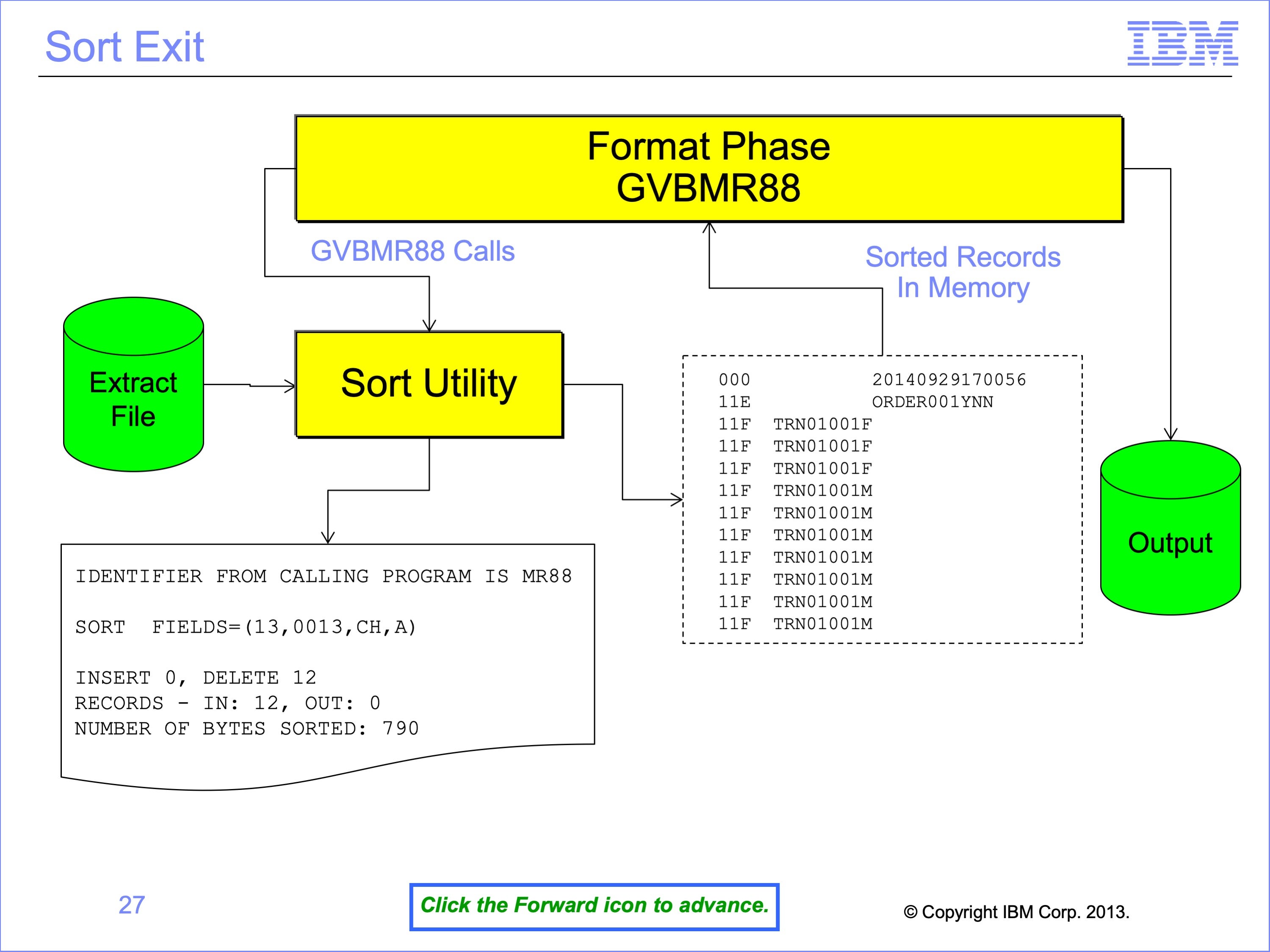
To avoid writing the sorted extract file, and then reading this file again for summarization and formatting, GVBMR88 calls the Sort Utility as a “Sort Exit.” This allows the sort utility to pass the sorted records to GVBMR88 a record at a time after completing the sort, instead of writing them to disk, thus avoiding a pass of the extract file. In other words, the sorted records are a virtual file that is never actually written to disk.
The Sort Utility also prints a control report. This example shows some of the key messages, including noting the utility is running as an exit to “MR88”, the sort parameters that were generated by the Extract Engine, the number of records sorted. Records are “deleted” from the virtual file by GVBMR88 as it produces the final output file.
Slide 28
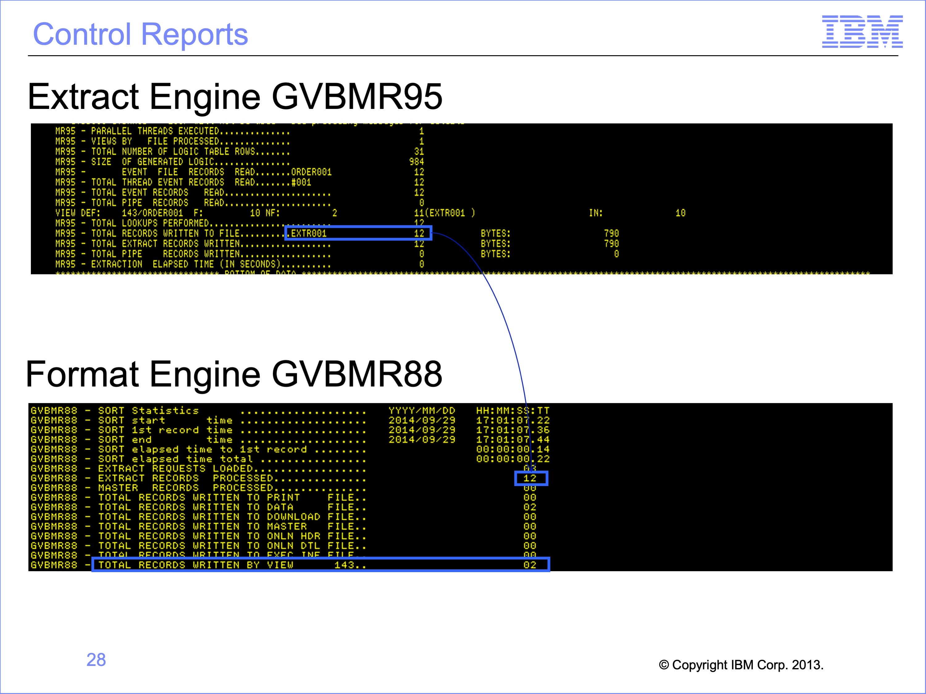
The Format Engine also produces a control report at the end of it’s execution. This control report shows the number of records read from the input file, the number of records written to various types of format files, and the number of records written to view specific output files. The total records read by GVBMR88 should equal the number of records written by the Extract Engine.
In this example, 12 records were written to the extract file, and all 12 were read by the Format Engine. The final output file for view 143 was 2 summarized records.
Slide 29
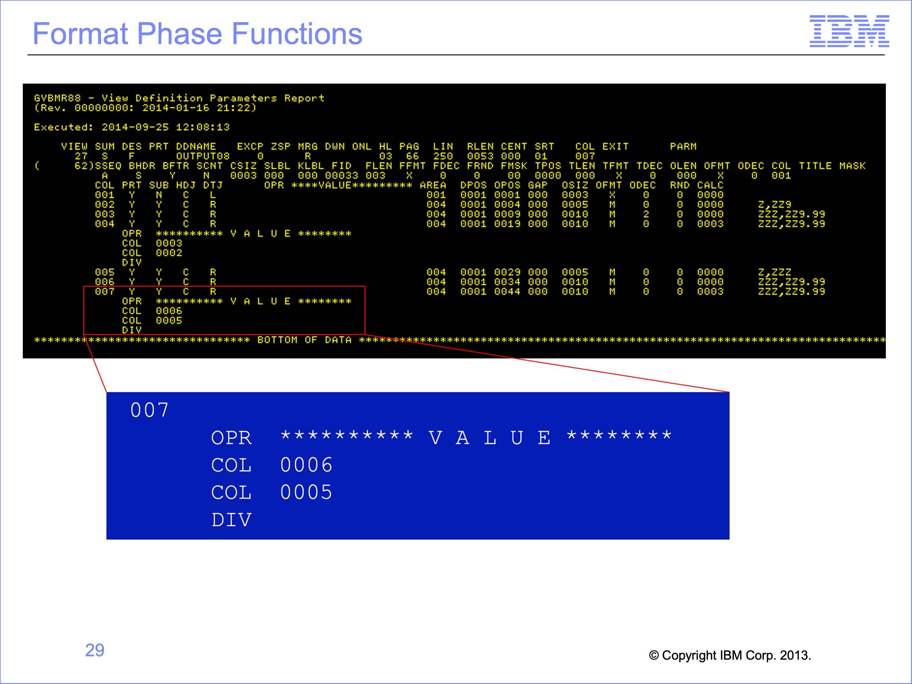
Not all SAFR functions are specified in the logic table. For example, column calculations using column numbers are not specified in the logic table. Other functions include column spacing, creating hard copy report formatting, subtotaling, and summarizing. All these parameters are passed to GVBMR88 in the View Definition Parameter or VDP file and performed during the format phase.
This screen shot shows the VDP parameters used by GVBMR88, including column definition sizes and formats. This report is printed at the end of the Format Phase. The highlighted area for Column 7 contains a column calculation. The logic for this calculation is “Column 6 divided by Column 5”
Slide 30
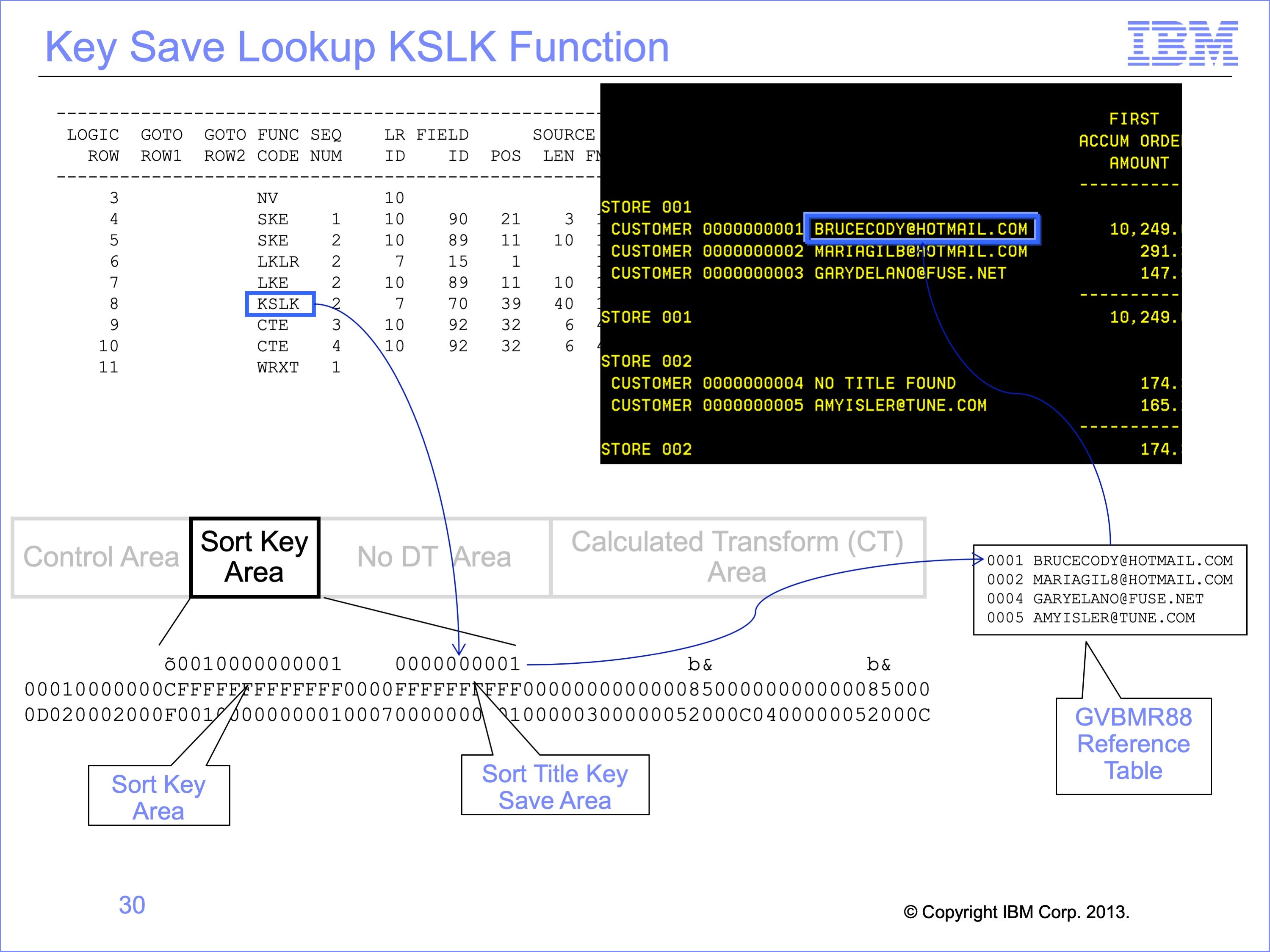
One last specialized Logic Table function should be mentioned. The Format Engine does one type of join, for one format of output: Sort Titles (descriptions of sorted key values) on hard copy reports. These GVBMR88 look-ups though are not multiple level joins. They are simply the last step in the Join process to obtain the sort title. The Format Engine does not perform any of the LKLR, LKE or other functions to do the join. Rather it receives the fully formed key as an area of the Sort Key Area. Saving this key in the sort key area of the extract record. The Format Engine then performs the lookup to find the sort title.
In this example, the KSLK function save the lookup key of 0001 into the Sort Title Key Save area of the extract record. GVBMR88 then uses this key to search for customer e-mail addresses to place next to customer numbers in the hard copy report.
Slide 31
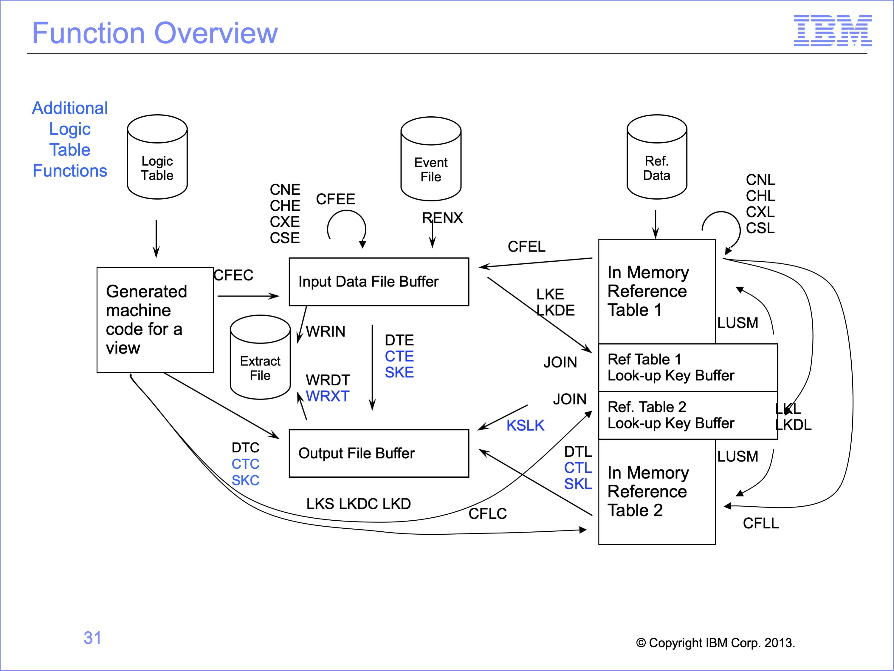
This logic table has contained the following functions:
- SK functions, including SKC, SKE, and SKL, to build Sort Keys.
- CT functions, including CTC, CTE, and CTL, to build Calculated Transformations
- WRXT, which writes the extract record to a standard extract file
- KSLK, which saves the Look Up Key for a Sort Title on hard copy reports
Slide 32
This module described Format Phase views. Now that you have completed this module, you should be able to:
- Describe uses for Format-Phase Views
- Read a Logic Table and Trace with format-phase views
- Explain the Function Codes used in the example
- Debug format-phase views
Slide 33
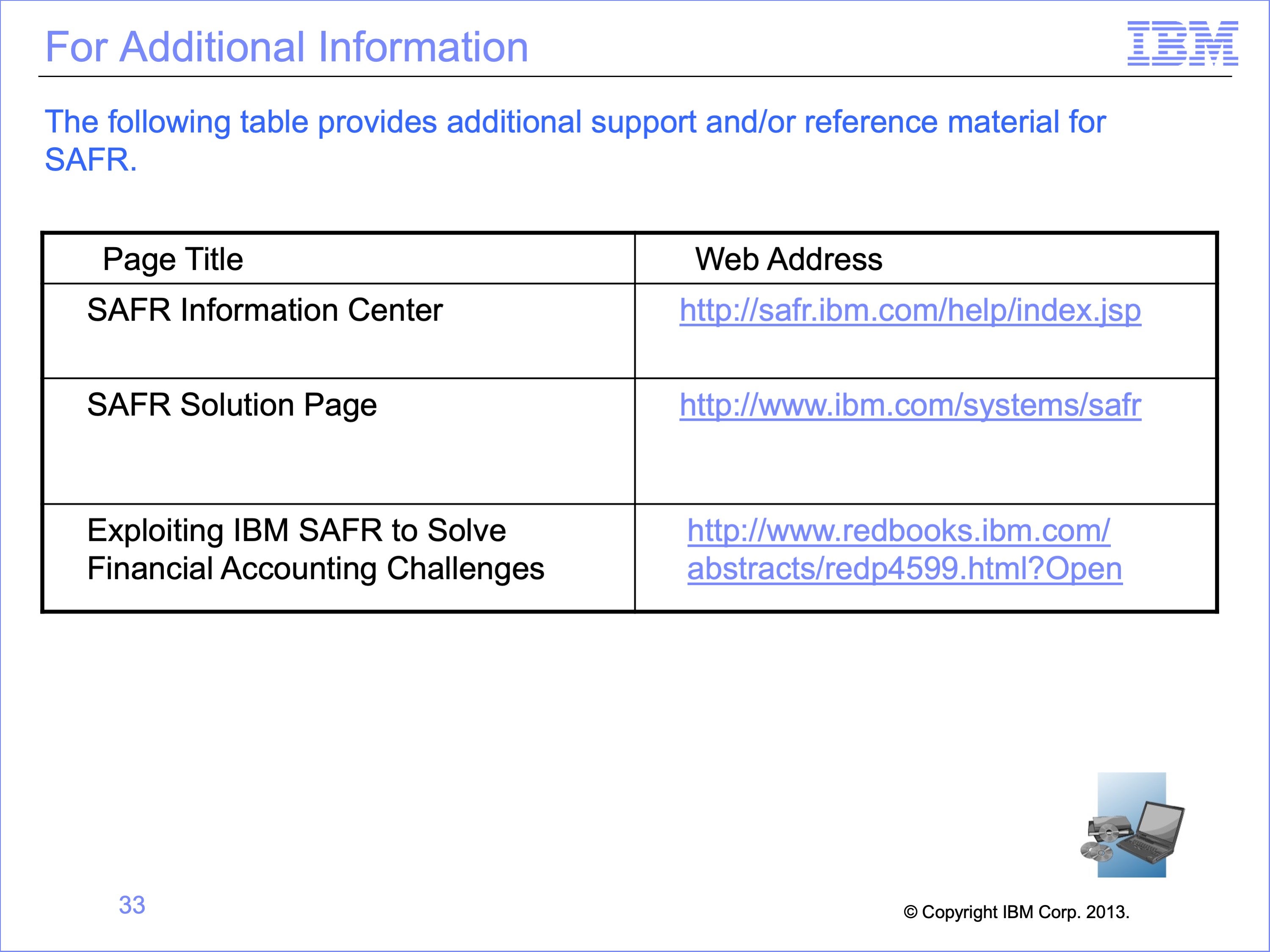
Additional information about SAFR is available at the web addresses shown here. This concludes Module 17, Format Phase Views
Slide 34