The slides from the following video are shown below.
Slide 1

Welcome to the training course on IBM Scalable Architecture for Financial Reporting, or SAFR. This is Module 12, The Single Pass Architecture
Slide 2

Upon completion of this module, you should be able to:
- Describe the Single Pass Architecture
- Read an Extract only Logic Table and Trace
- Explain the Function Codes used in the example
- Debug AND and OR selection logic
Slide 3

The prior modules covered the function codes highlighted in blue. Those to be covered in this module are highlighted in yellow.
Slide 4

One of the most powerful features of SAFR is the single pass architecture. Input / Output processing or IO is often the slowest part of data processing, at times thousands of times slower than other functions. SAFR’s single pass architecture allows for a single read of the input data to produce many different outputs. Each output can be unique, as specified by individual views.
Slide 5

In this module, we will continue to build on the prior lesson, where a Copy Only view was processed alone. In this module, we will add an Extract Only view. Both of these views do not require the Reference and Format phases of the SAFR Performance Engine.
In this example, we’ll also execute the Copy View at the same time as the Extract Only View, demonstrating how the SAFR Single Pass Architecture works. The logic table will contain two views in one logic table. The Extract Engine, GVBMR95 will produce two outputs.
Slide 6

Instead of copying all fields on the input records to the output files, the Extract Only view writes selected fields to the output file. Any field may be written to the extract file, in any order, regardless of the order or position on the input file. Field formats may also be changed, for example changing a zoned decimal to a packed field format. These columns will cause DTE Logic Table functions to be generated in the Logic Table. Constants can also be written to the output file.
Constants use DTC functions in the Logic Table. Extract only views can also contain looked-up fields, which will be explained in the next module, and which generate DTL logic table function codes.
In our example, columns 1, 2, 3 and 5 of the view will extract the Cost Center field, Legal Entity, and the Account and Record Count respectively.
Slide 7

Logic text in Column 4 will cause the output file to contain a constant of either the value Asset Account or Liability Account. “AssetAcct” will be assigned if the account number field on the input file contains the values “111,” “121” or “123”. Otherwise column 4 will contain the Liability account constant “which is the value “LiabAcct”. This logic text will create multiple CFEC functions, introduced in the prior module.
Slide 8

Column 6 contains Logic Text that tests the input amount field. If the amount is a valid number (is numeric), it will be written to the output file. If the amount on the input file is not numeric, a constant of a zero will be written to the output file. This logic will generate a CNE function in the logic table.
Slide 9

This is the Logic Table generated for both the Copy View and the Extract Only view.
The portions of the logic table generated for the Copy Only view example in the last module remain mostly unchanged. It includes the HD Header, RENX Read Next, and logic table rows 3, 4 and 5. The last two rows of the logic table, the ES End of Source (sometimes called End of String) and EN End of Logic Table functions are very similar as well. Only the row numbers on these last two rows have changed
Slide 10

Our new Extract Only view, number 3262, is inserted in the middle of the logic table. So each record read from the input file will first be passed through all the Logic Table Functions for the Copy Only view, and then through the logic table functions of our new Extract Only view.
Slide 11

Our Extract only view again includes an NV – New View function, and concludes with a WR function. In this case, instead of a WRIN function which writes the input record (makes a copy), it is a WRDT function, Write the Data area of the extracted record.
Slide 12
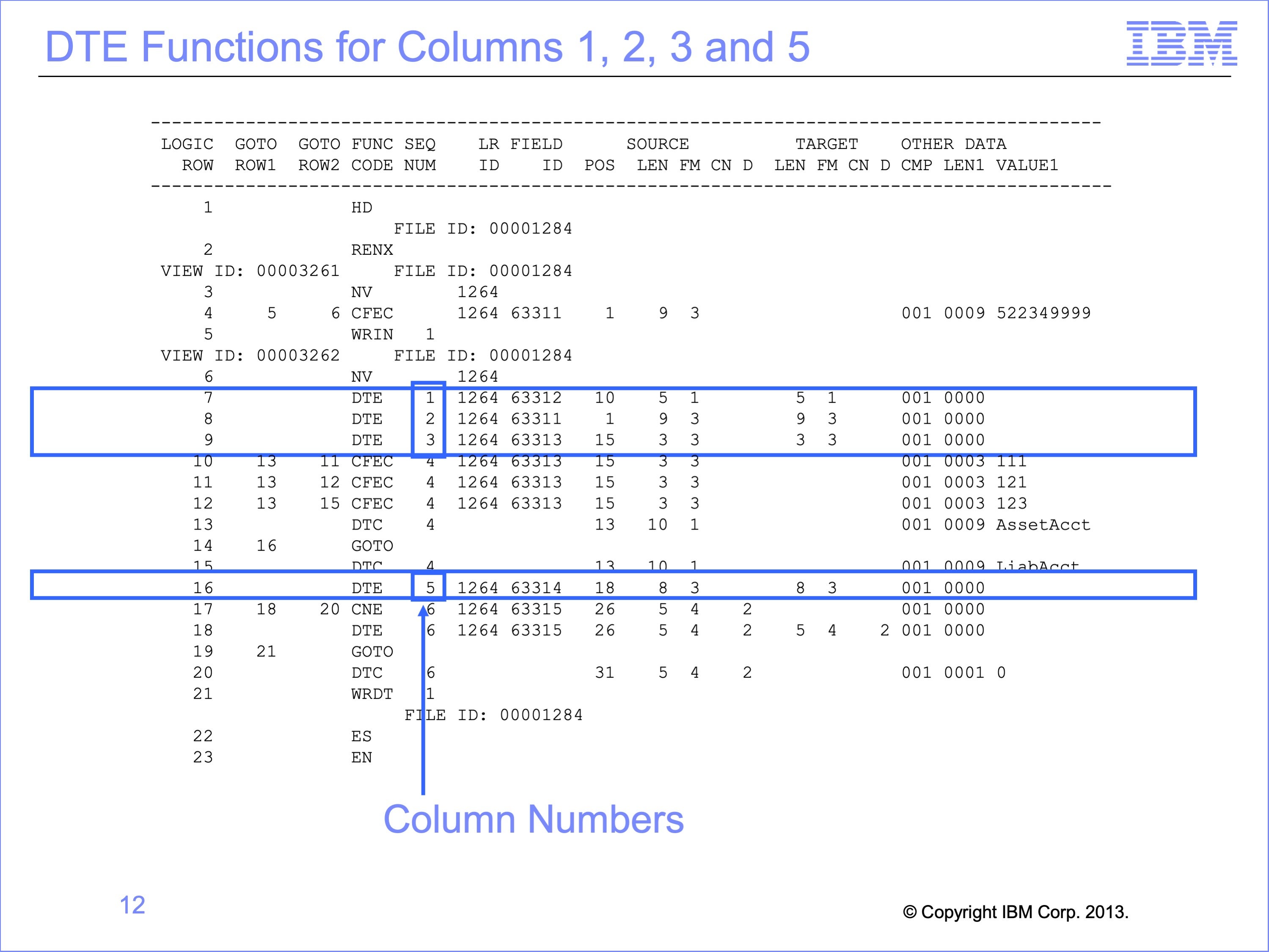
Columns 1, 2, 3 and 5 simply move fields from the input file to the output file. These columns cause DTE functions to be generated in the logic table. The DTE function simply moves data. The “DT” is derived from “Data” , the “E” means the source is the input Event File field.
Each DTE function is followed by a Sequence Number. The Sequence Number for each DTE shows the column number causing that logic to be generated.
Slide 13
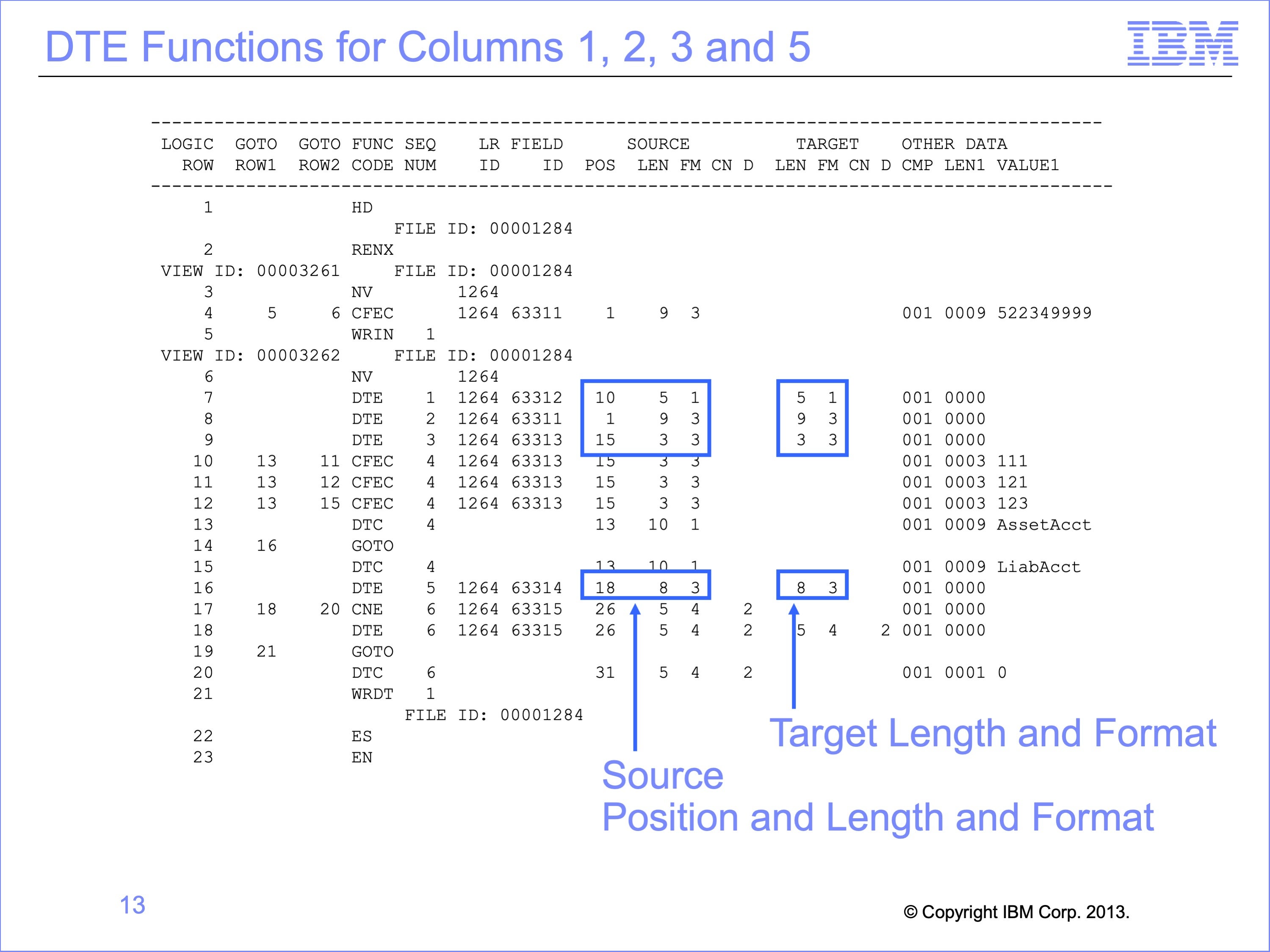
Each DTE row also contains the position and length in the source Event file. These positions, lengths, formats and numbers of decimal places are taken from the Logical Record describing the input file.
Each DTE row also contains the length and format to be placed in the output file. A difference between the length, format, or number of decimals between the Source and Target columns indicates SAFR has performed a transformation before writing that field. In this example no transformations occurred.
The report does not show the position in the output file. The start position in the final output file is shown in the view editor of the Work Bench. But the final output file position may be different than the extract file position, depending on the view type. The extract file position can be calculated by accumulating the lengths of all preceding column outputs.
Slide 14
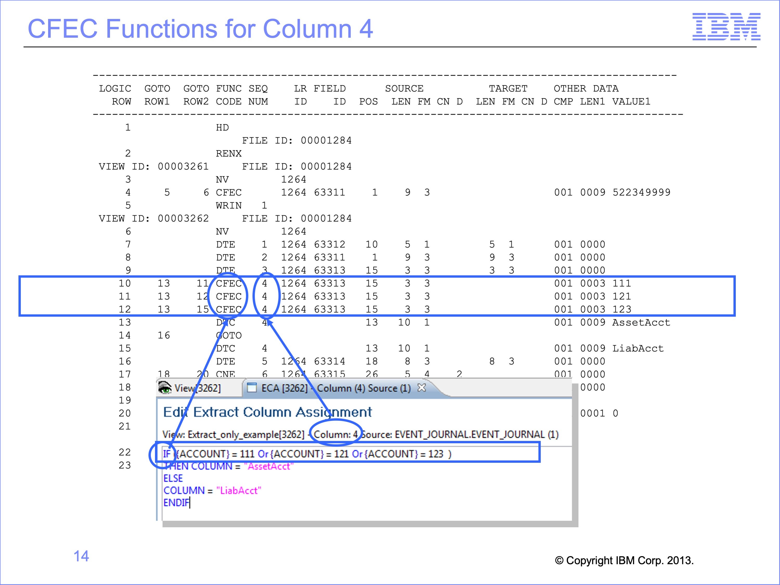
The first part of the Logic Text in Column 4 contains the text “If Account = 111 or Account = 121 or Account = 123”. This clauses causes multiple CFEC functions, (Compare Field, from the Event file to a Constant) to be generated in the Logic Table. The CFEC functions in logic table rows 10, 11 and 12 are generated by this specific IF statement.
The Sequence Number field of the report shows the column number that contains the logic that created the CFEC. In this instance, the logic is contained in column 4 of the view.
Slide 15
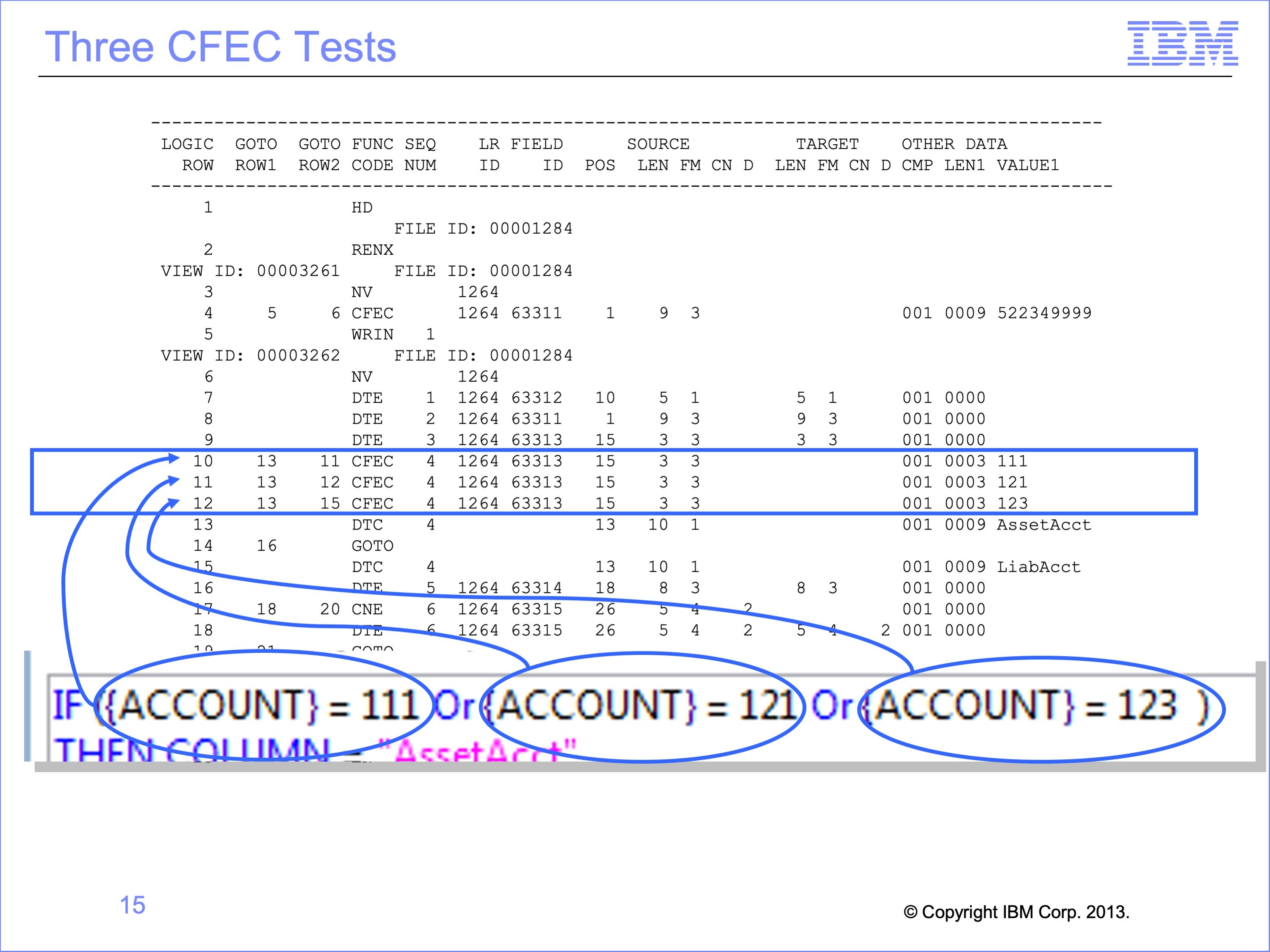
CFEC functions work together to complete a complex OR or AND test. In this example, the “OR” statements caused three CFEC functions to be created.
The first test for Account equal to 111 is performed on Logic Table Row 10. The second test for Account equal to 121 on Logic Table Row 11, and the third test for Account equal to 123 on Row 12.
Slide 16
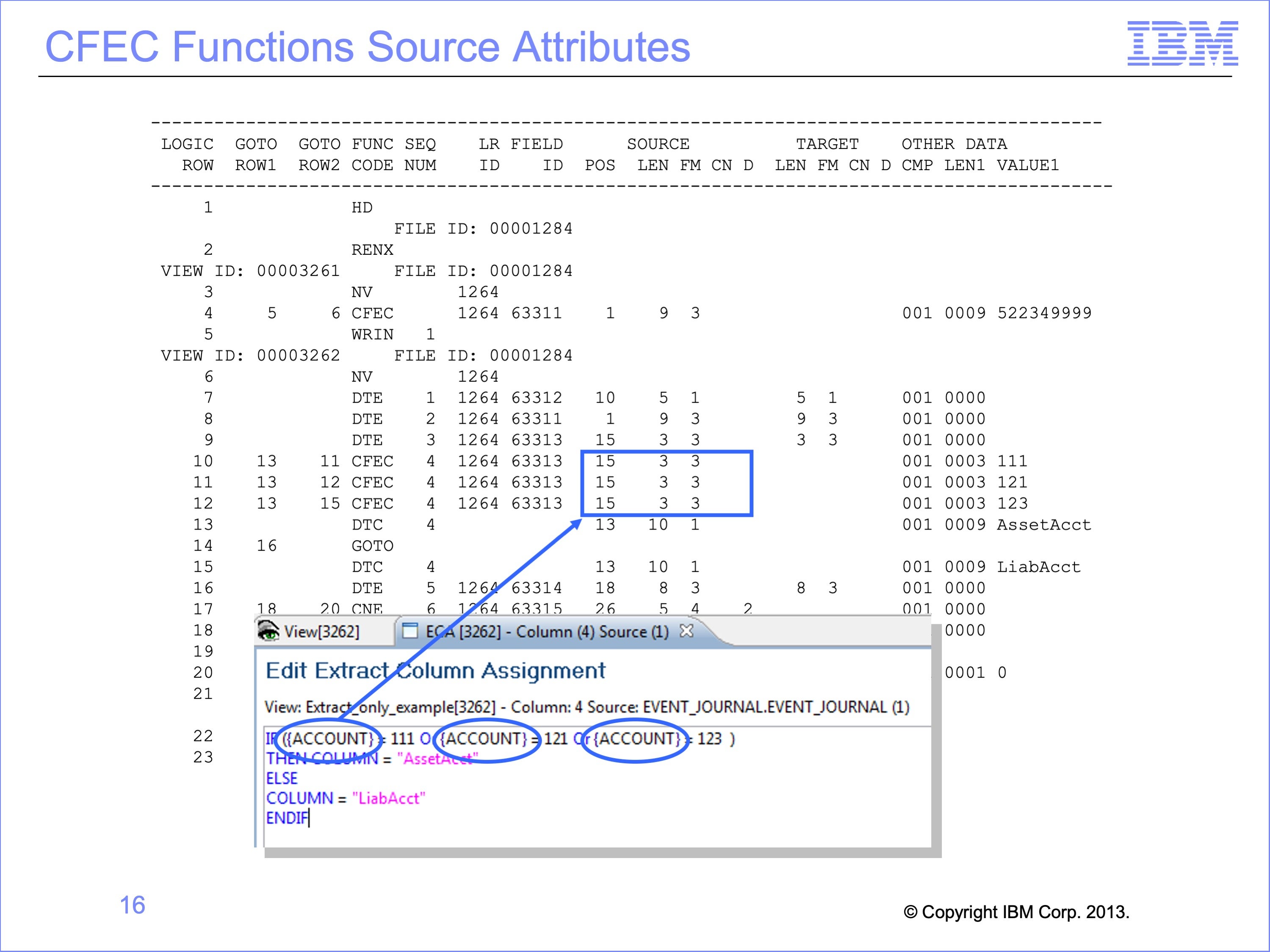
Because each CFEC tests the ACCOUNT Field—the “E” or Event File field portion of the CFEC—the position, length and format of the ACCOUNT field is shown in the Source attribute columns. Because the ACCOUNT is used three times in the logic text, the same position, length and format are used on all three CFEC rows.
Slide 17
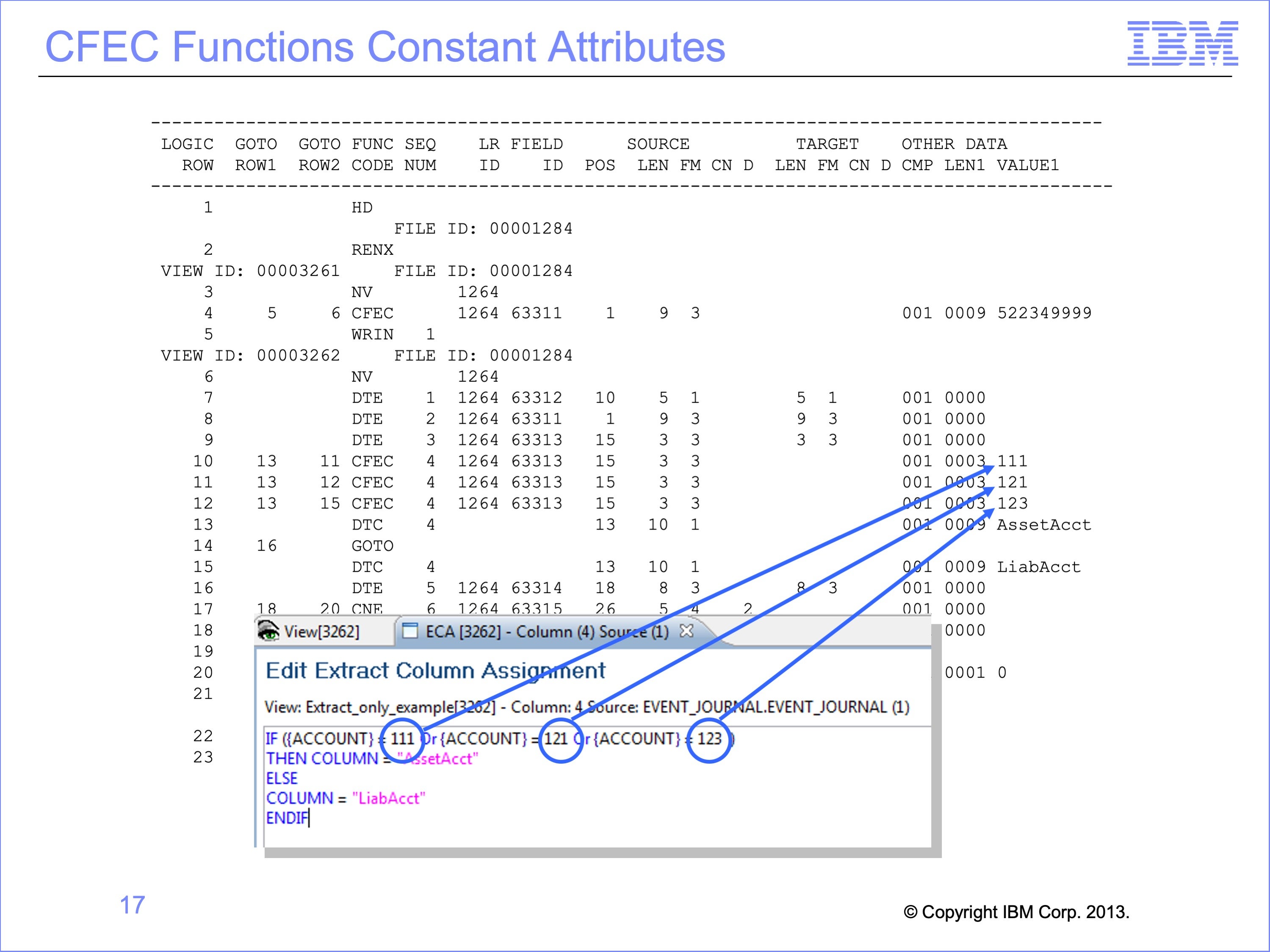
The constants—the second “C” of the CFEC—are also placed in the logic table. These three constants are placed at the end of the respective logic table rows. These three constants all are a comparison type of 001 which is equal, and are all 3 bytes long
Slide 18
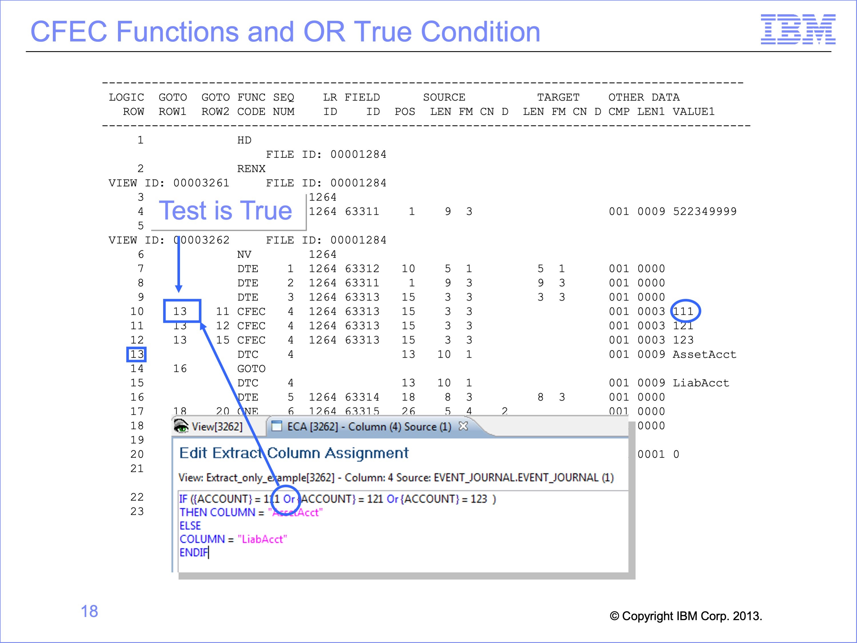
The OR condition of the logic text determines the numbers placed in the GOTO rows. If the value in the Account field on the input Event file is “111”, then the result of the first test is “true” and the record should be selected for additional processing within the column. Thus executing will jump to row 13, as specified in the Goto Row1 which is the true condition branch.
Slide 19
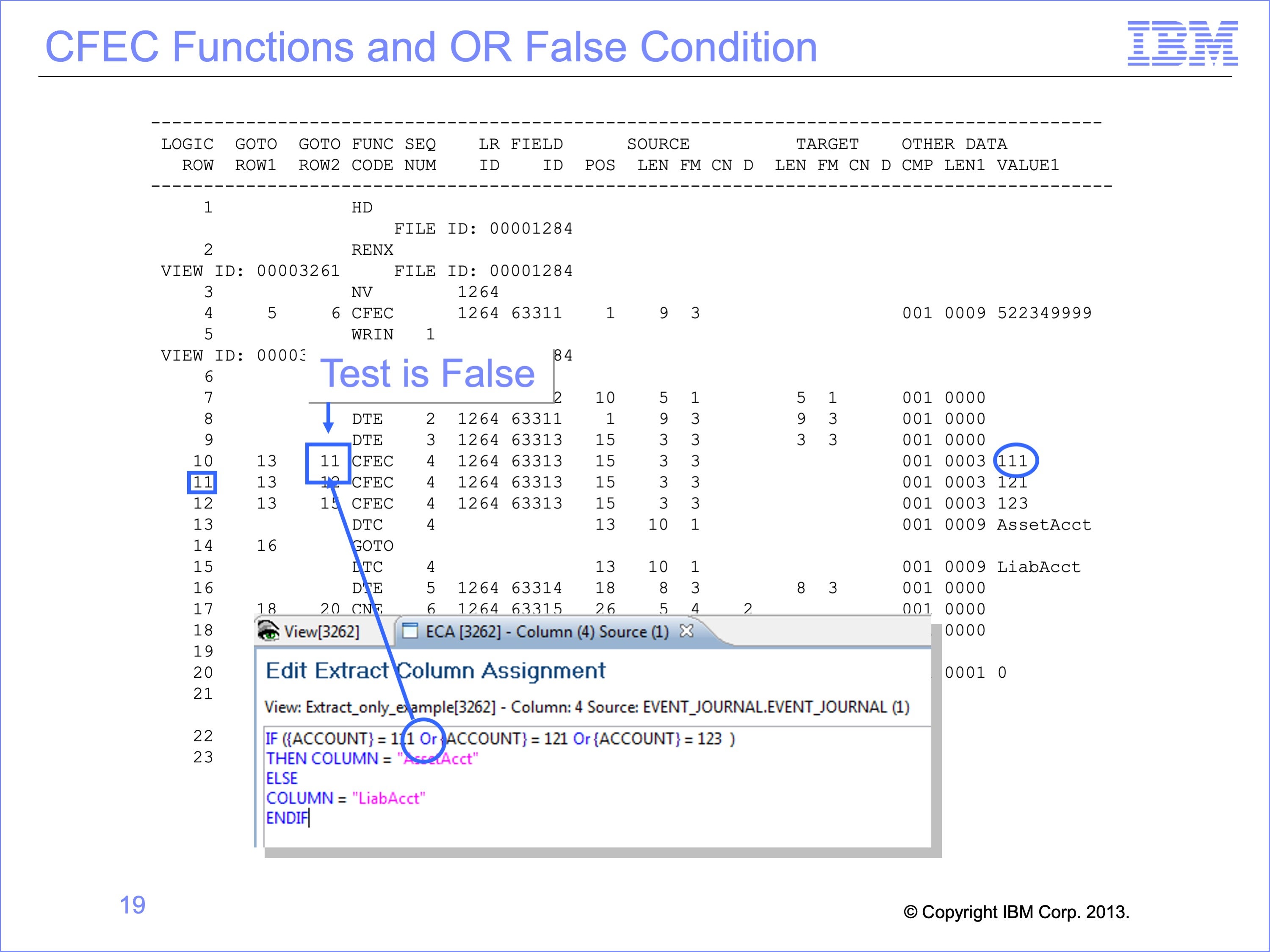
If the logic table row tests false, then the other tests of the OR condition must be evaluated, including testing for “121” or “123”. Thus the False GOTO Row is row 11, the next logic table row, where the next CFEC function will test against a constant of “121” rather than “111”
Slide 20
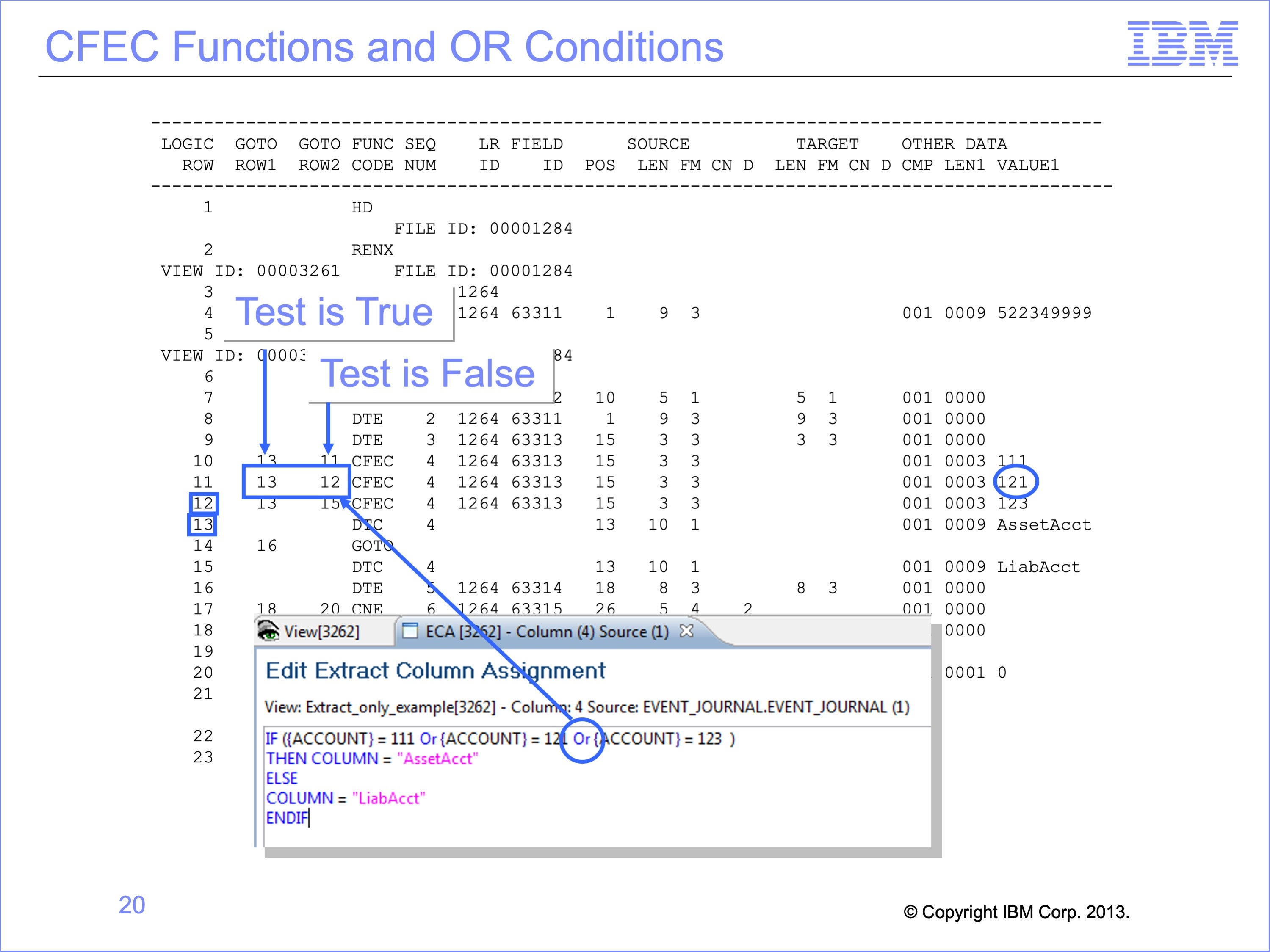
The second OR condition creates a similar pattern on the next CFEC function, testing against constant “121” on logic table row 11. If true, then the next row to be executed is row 13 where the column will use the input record in some way. If the value in not “121”, then the next row executed is row 12, the next OR condition to test against value “123”.
Slide 21
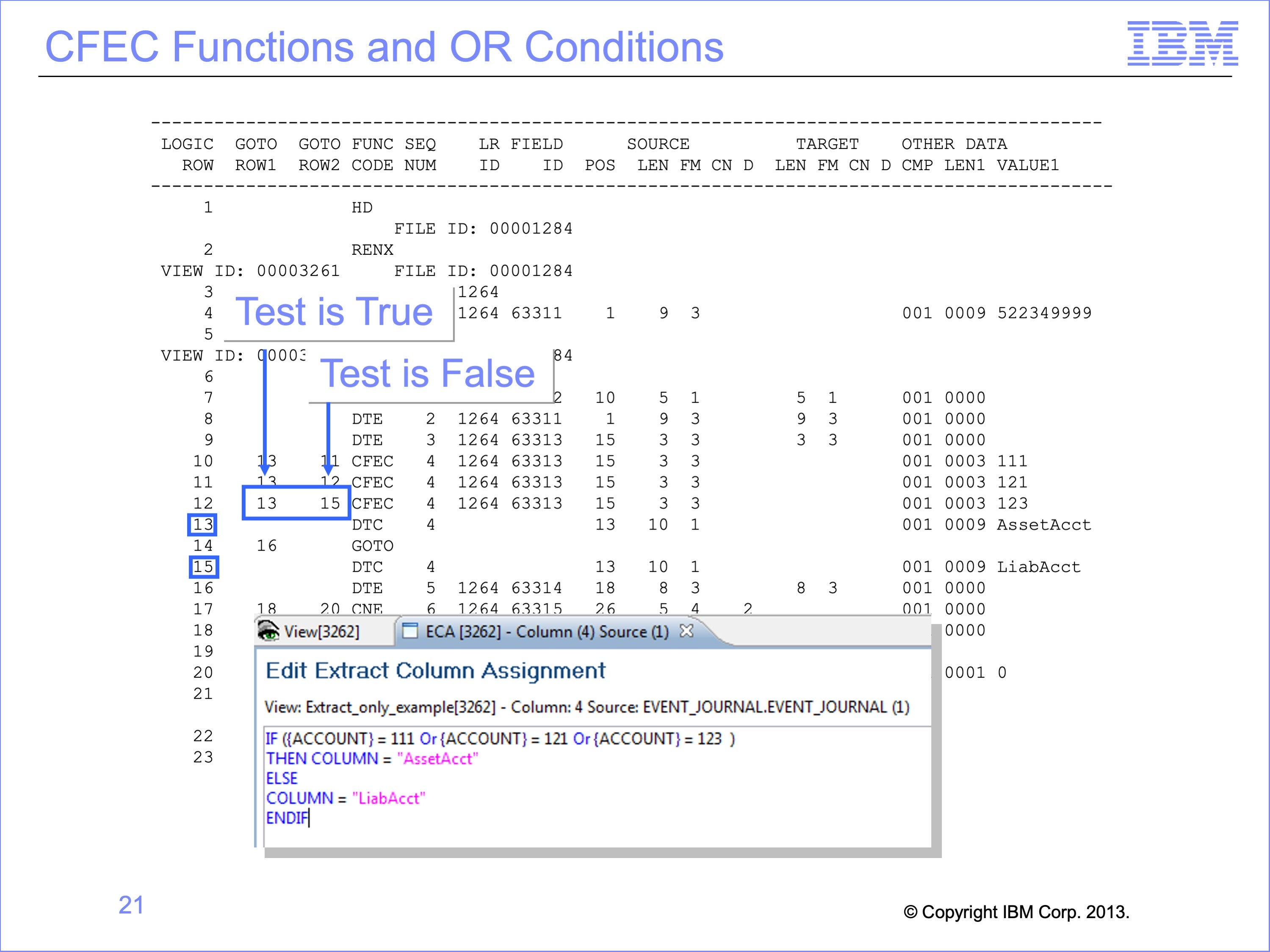
Row 12 tests the Account field on the input Event file for value “123”. If it test true, then the next row to be executed is again row 13 which will move a constant to the output record.
If the value in not “123”, then the next row executed is row 15 which means the else condition for the column value will be used.
Slide 22
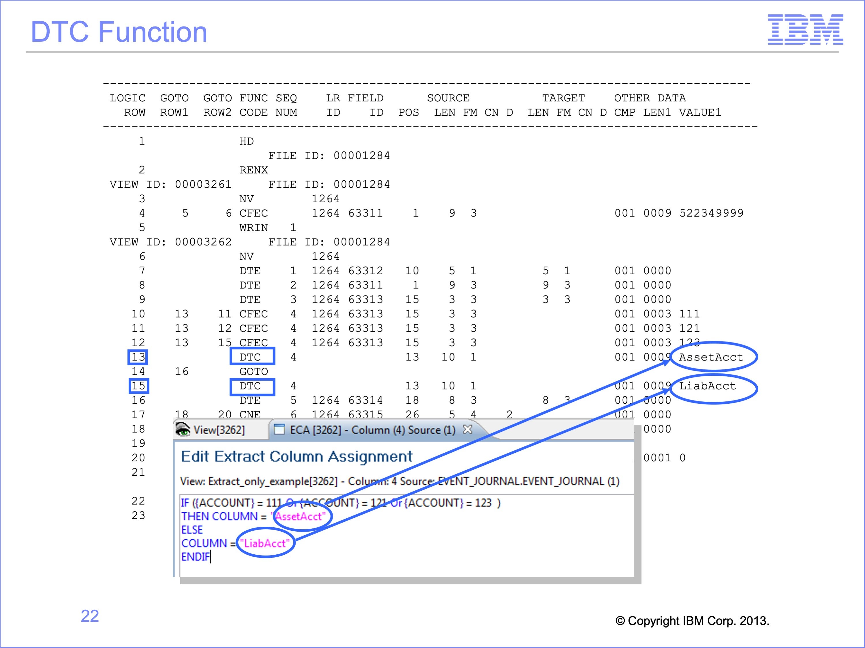
The THEN and ELSE portions of the logic text cause additional rows to be generated in the Logic Table. If a field was to be moved from the input to the output file, they would be DTE functions, like those generated for columns 1 and 2 and others. In this example, constants are to be moved to the output record, so DTC functions are generated, DTC meaning Data from a Constant.
Logic Table rows 13 and 15 are both DTC functions. Row 13 places the constant for Asset Account in the output file if any of the CFEC functions tested true. Only if the ACCOUNT field on the Input File has the value “111”, “121” or “123” will the output column receive the value of “AssetAcct” in it.
On the other hand, row 15 places a value for Liability Accounts. It is executed if ALL CFEC tests are false. Thus any ACCOUNT value besides those three tested will result in a value of “LiabAcct” in column four of the output file.
Slide 23

If all rows in the Logic Table were executed sequentially in order without skipping any rows the constant of Liability Account would overwrite all the Asset Account constants place in the output record. To prevent this, a GOTO row is used to skip the DTC for Liability Account whenever an Asset Account is used.
In our example, Row 14 is a GOTO row. If Row 13 placed the Asset Account value in the output file, the program naturally falls through to row 14. The Logic Table then tells the program to jump to row 16, skipping row 15. This prevents the value of Asset Account from being overwritten with the Liability Account constant.
Slide 24
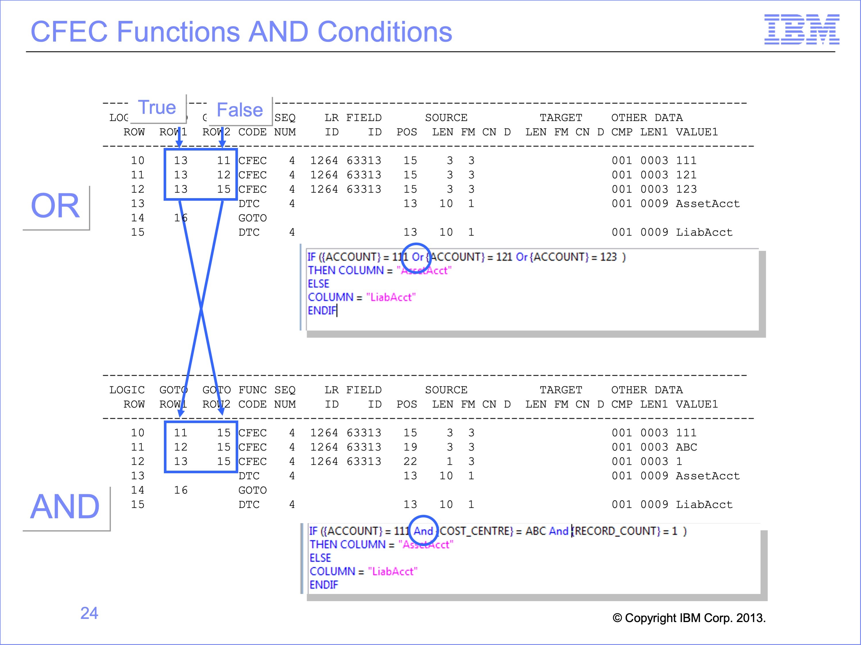
With OR logic, all three CFEC rows execute row 13, which places the Asset Account value in the output. If any one of the rows is true, Asset Account is placed in the output.
If our logic text were changed, and we used AND logic to test three different fields, our GOTO ROW1 and ROW2 would be swapped. AND conditions require that all three rows test true. The effect is that the True and False row numbers switch places for AND verses OR logic.
Slide 25

With AND logic, a true condition on each CFEC causes the logic to continue to the next row of the logic table to continue the test. After the final test of the AND condition, if all tests have proven true, the DTC function on Logic Table Row 13 is executed to build the Asset Account constant. If any of the CFEC functions prove untrue, execution continues at Logic Table Row 15, the Liability Account DTC function.
A common debugging problem occurs if logic text requires the same field to contain multiple values by using AND when OR was intended. The same field on a single input record can never contain multiple values. For example the field Account can never equal “111” AND “121”. The condition would always prove false. Using the Logic Table to read how the logic is interpreted can help uncover these types of problems.
Slide 26
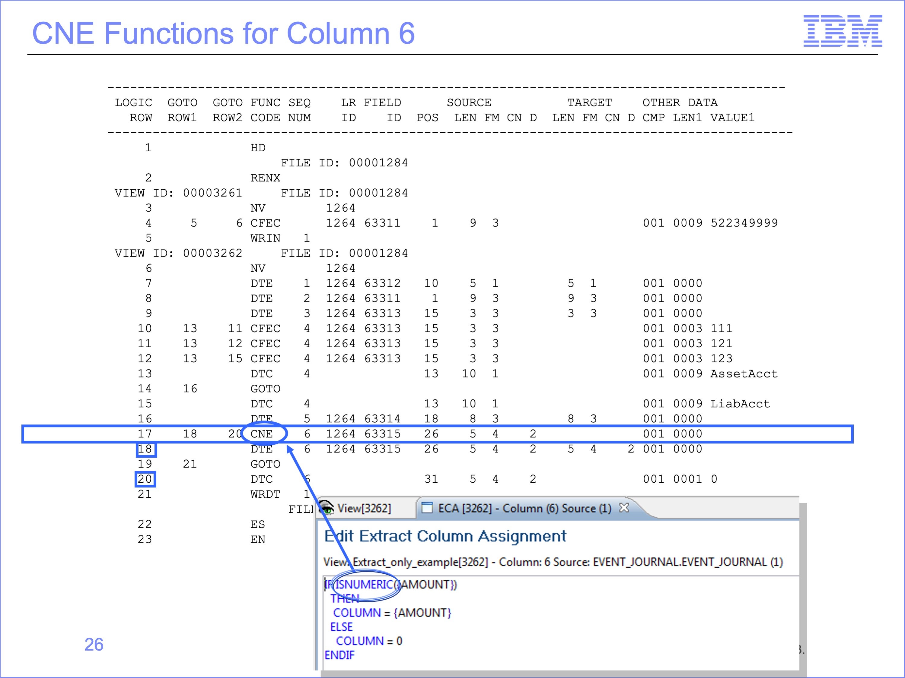
The last column of the view tests to ensure only valid numeric values are placed in the output file using the Logic Function “ISNUMERIC”. The “Is Numeric” function in Column six of the view generates a CNE function, a Class Numeric test of an input Event file field. The CNE function is similar to a CFEC function. It tests a value and directs execution to the GOTO 1 or 2 rows depending on the results of the test.
The CNE function on row 17 in our example tests if the input field AMOUNT contains a valid numeric value. If so row 18 is executed. If the input field is NOT numeric, GOTO ROW 2 will cause row 20 to be executed.
Slide 27
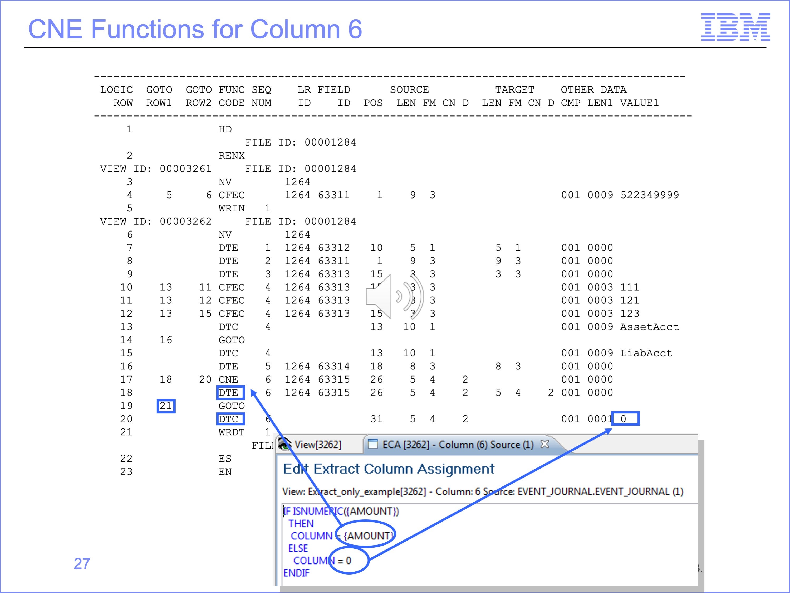
The THEN and ELSE conditions of Logic Text for column 6 perform different functions. The THEN Condition causes a field from the input file to be moved to the output file. The ELSE condition causes a constant of zero to be placed in the output file.
The true test of the THEN condition of the CNE test on row 17 will execute row 18, a DTE function, moving the Amount from the input record to the output.
The false ELSE condition on NON numeric causes row 20 to be executed, a DTC function placing a constant of 0 in the output file.
Slide 28
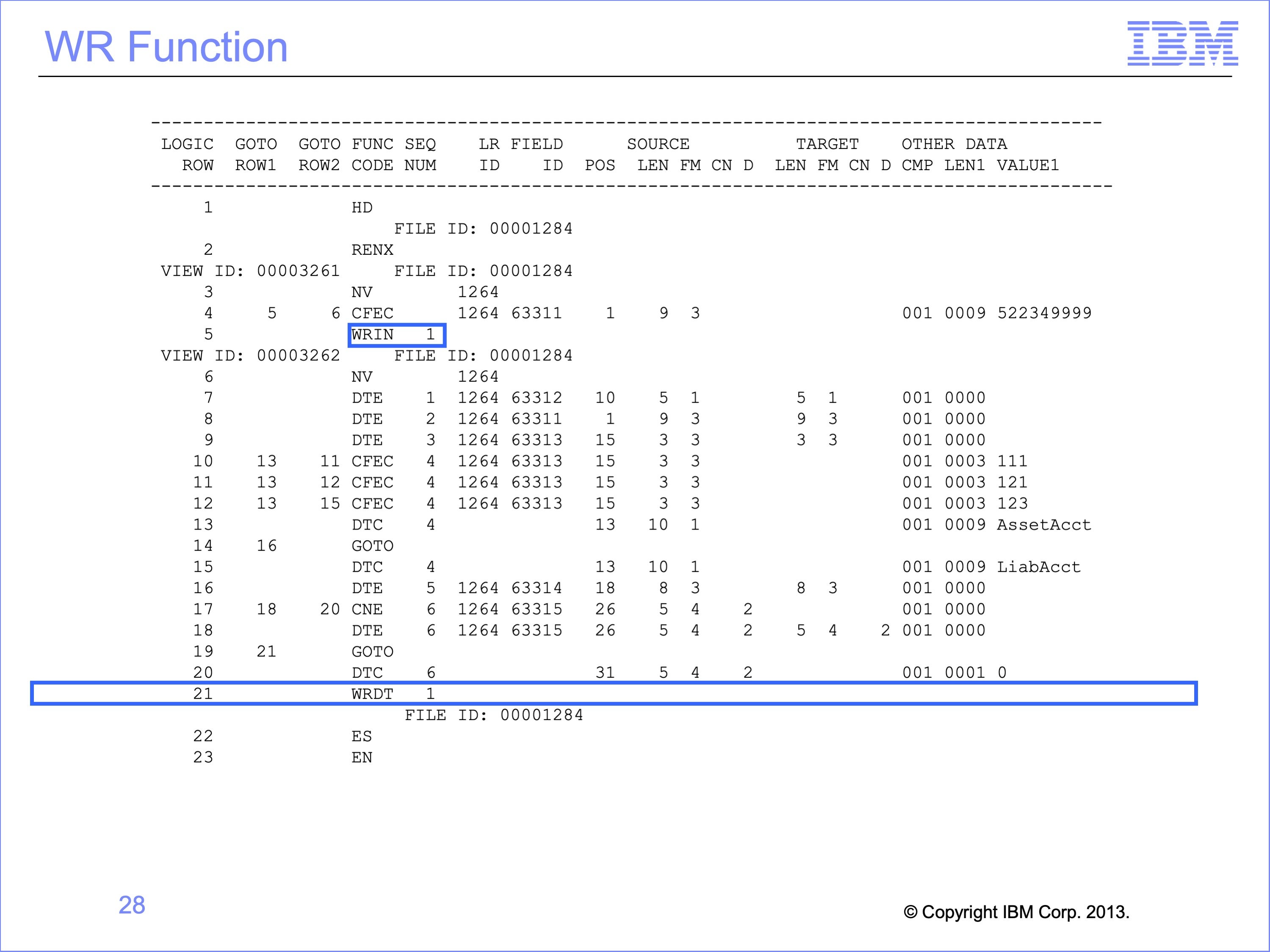
The final instruction of the Extract Only view is the WRDT function. This function is generated by default at the end of a view if there is no WRITE Logic Text function in the view. In these cases, it is always executed.
In contrast to the WRIN function which moves the Input Record to the output file, the WRDT function moves data from the Extract record area to the output file. All of the data moved to the extract record through the DT functions, both DTCs or DTEs, are actually written to the output file.
The WRDT is followed by a Sequence Number 1, meaning it writes its data to file number 1. This is the same file the WRIN function of the Copy View uses. Thus after the first input record is processed, the first record in the output file may be the copy of the input record selected by the Copy View, followed by the Extract Only data of the second view.
Slide 29
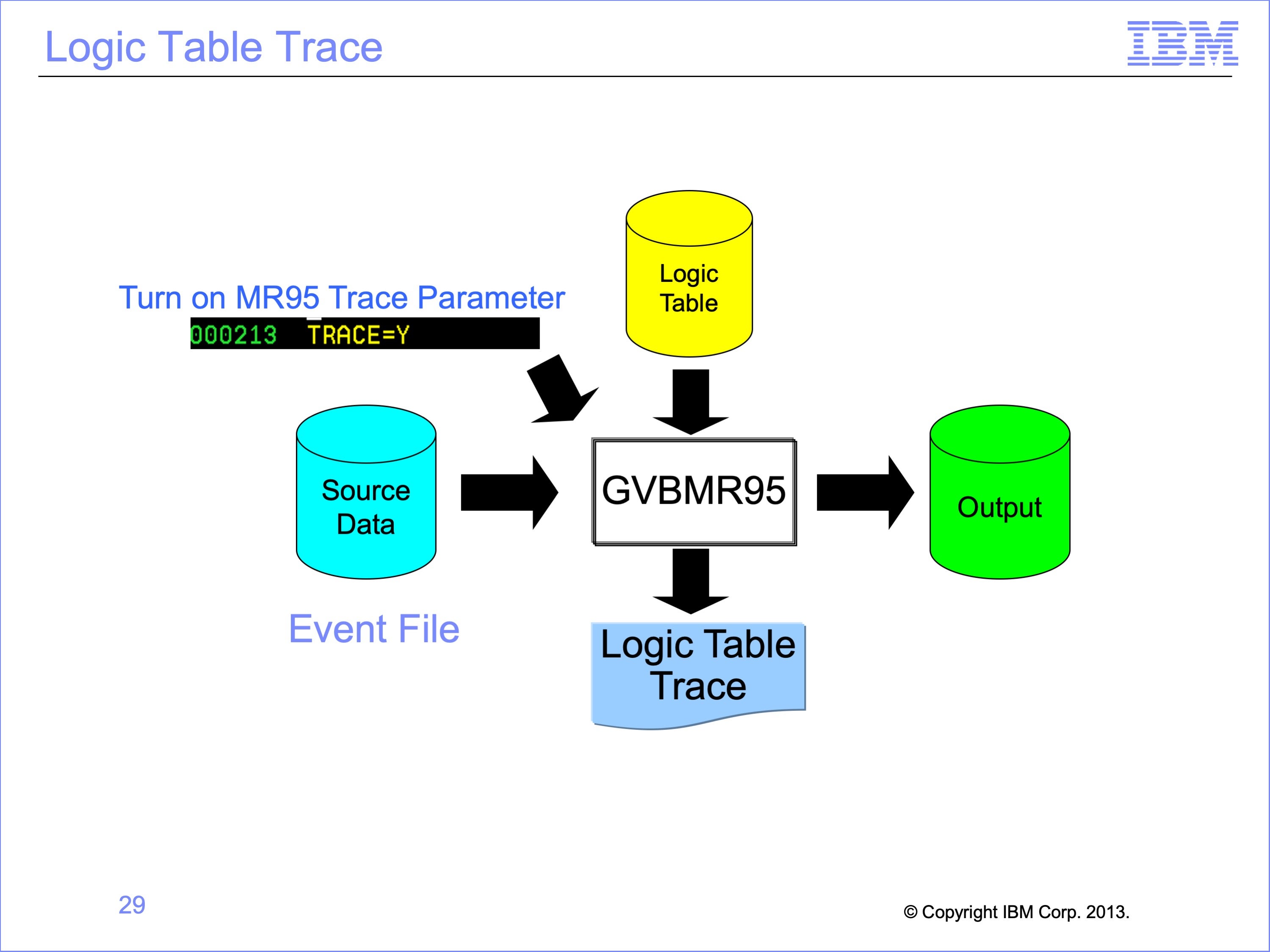
Having examined the Logic Table, let’s use our three record file again to see how it behaves through the trace process. Trace is turned on by setting the TRACE parameter to “Y” in the MR95 Parameters file.
Slide 30
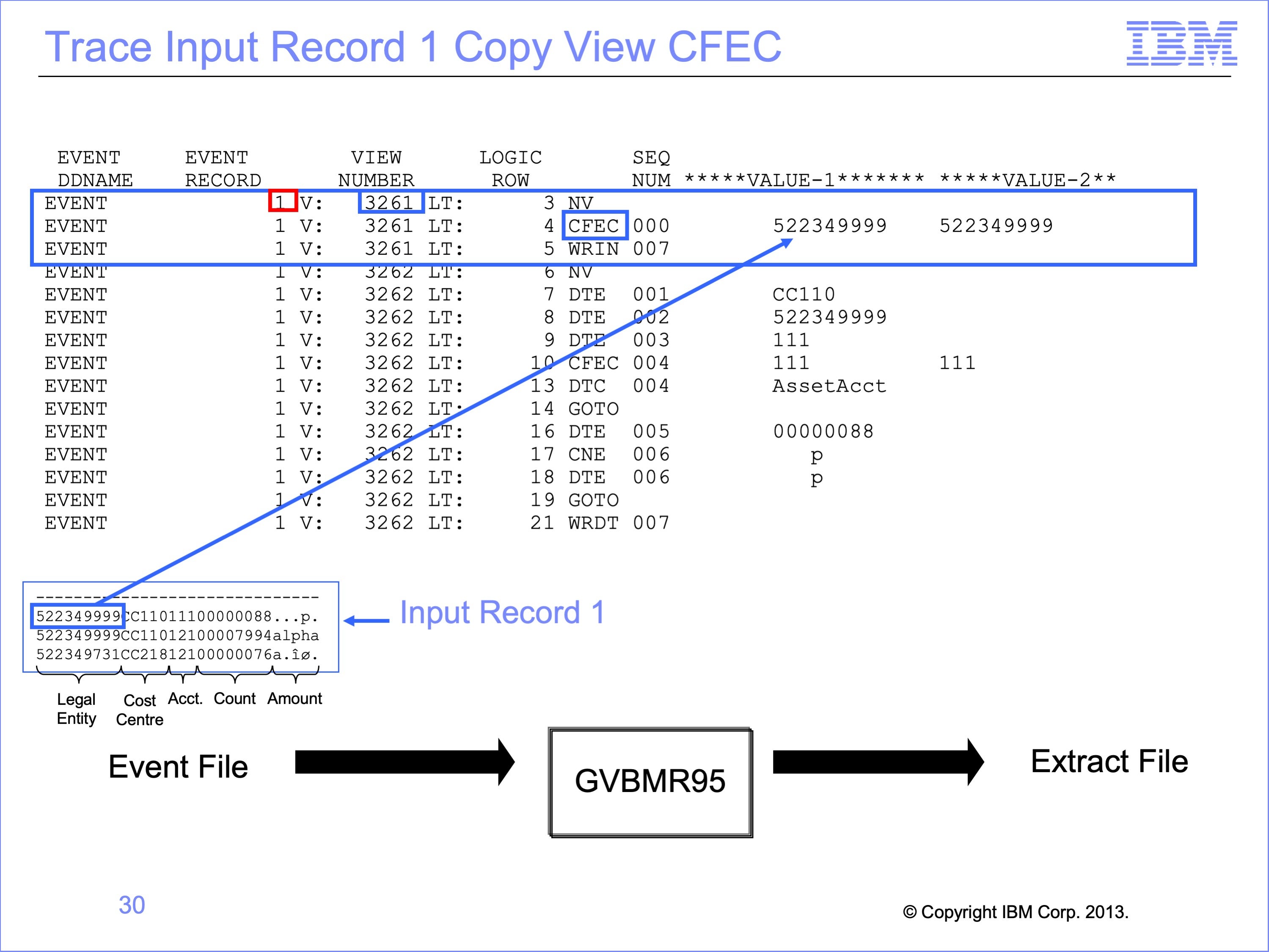
The first three rows of the trace are for view 3261, our Copy View from the last module. The first input record is compared against the constant in the CFEC function. The comparison is true, and so the next row of the logic table is executed.
Slide 31
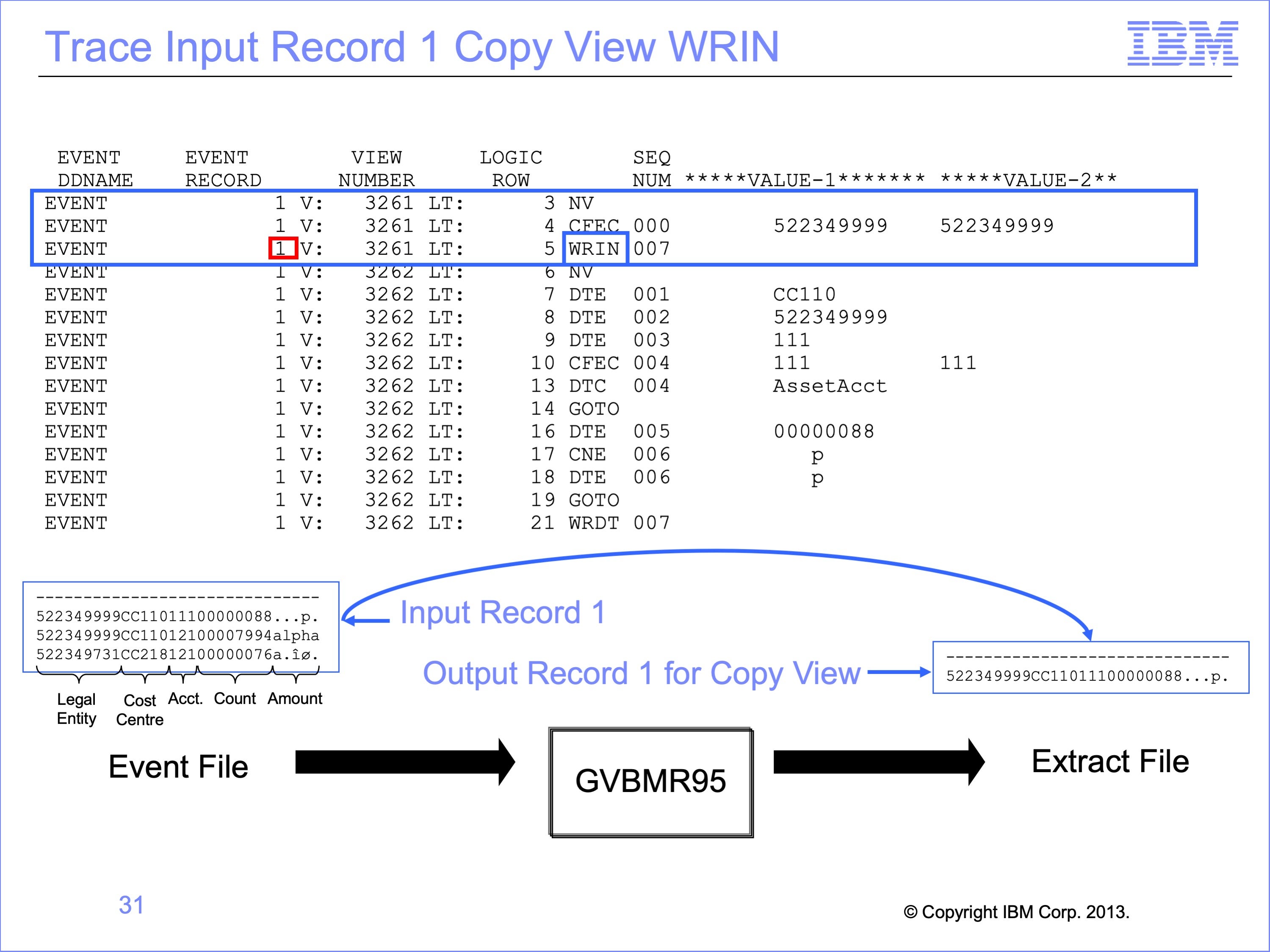
Because the test proved true, the input record is copied to the output file by the WRIN function.
Slide 32
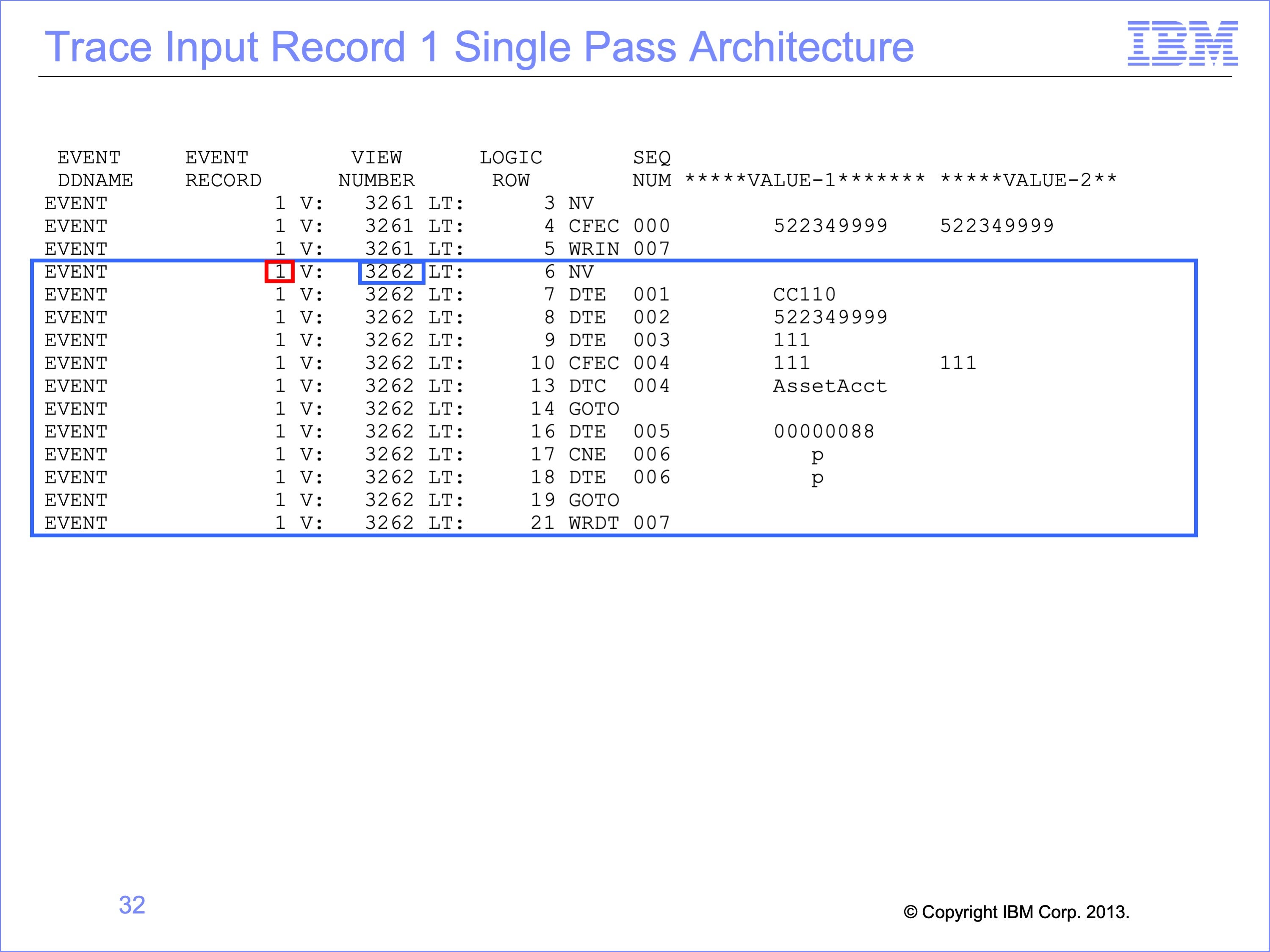
Because our SAFR execution included running more than one view, instead of looping to the next Event File record and the Copy Input View processing it, the input record is passed to our new Extract Only view, number 3262
Slide 33
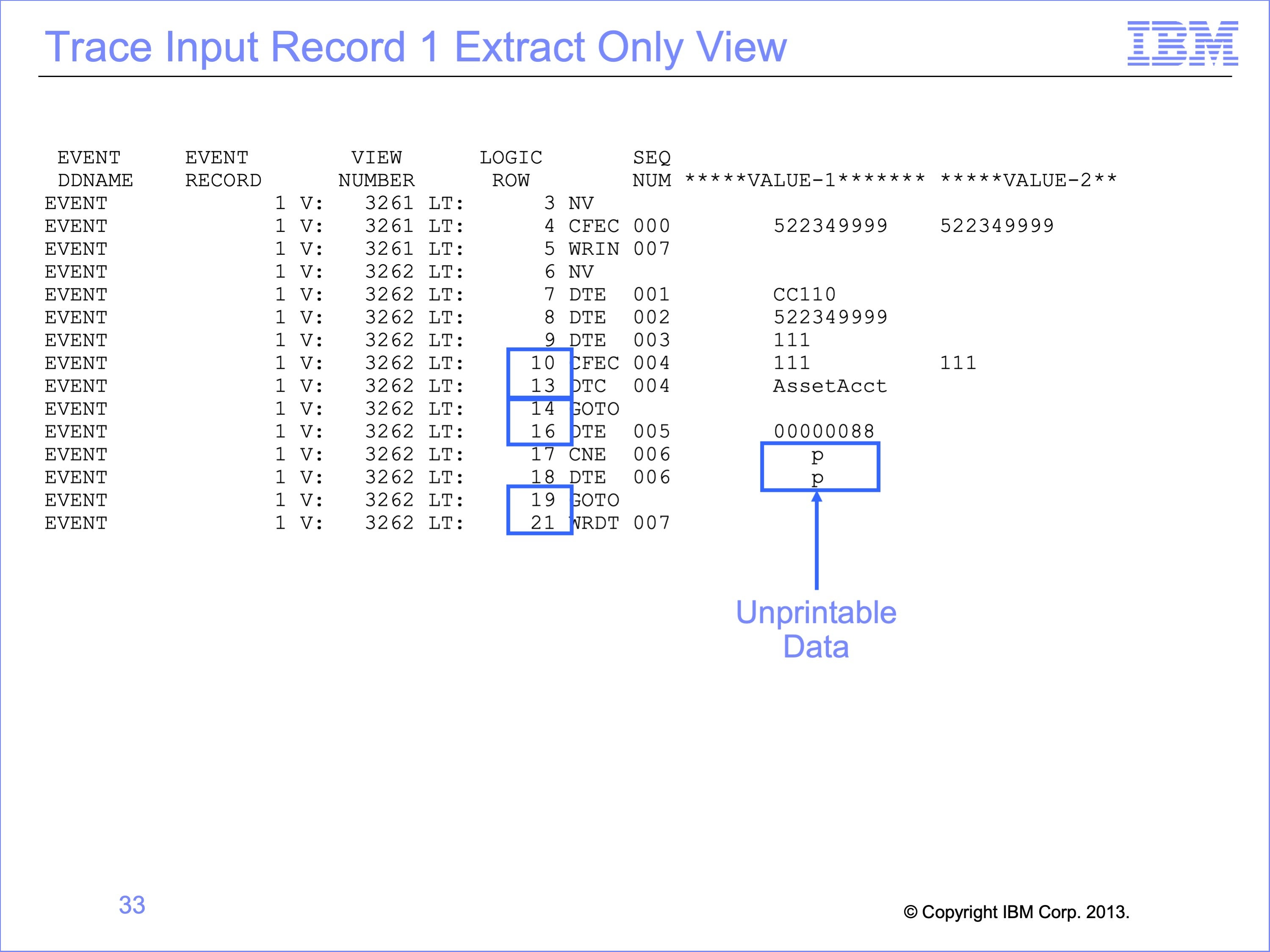
Note that some rows of the logic table are not executed as record 1 is processed in this example. Rows 11 and 12 are not executed because the OR condition in the Logic Text; the first condition proved true, so test 2 and 3 was not necessary.
Also, Row 15 which would have placed the Liability Account in the output file, was skipped by the GO TO Function on row 14.
Row 20 was also skipped, because the amount was a valid number, so it was not replaced by a constant zero.
Note that the trace does not convert Packed and other “un-printable data” to a printable format. The number tested on row 17 appears to print as a “p”, but if viewed in HEX mode, will display as a valid packed number based upon the format of the field used in the Numeric test.
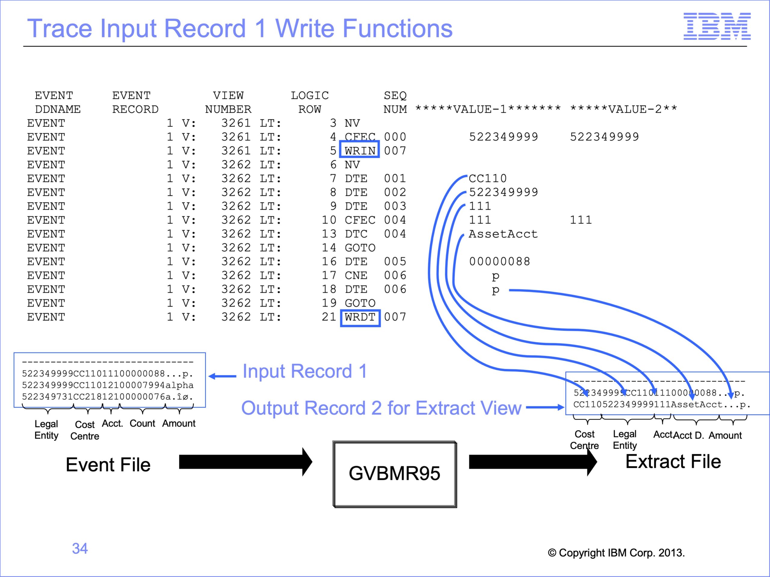
Slide 34
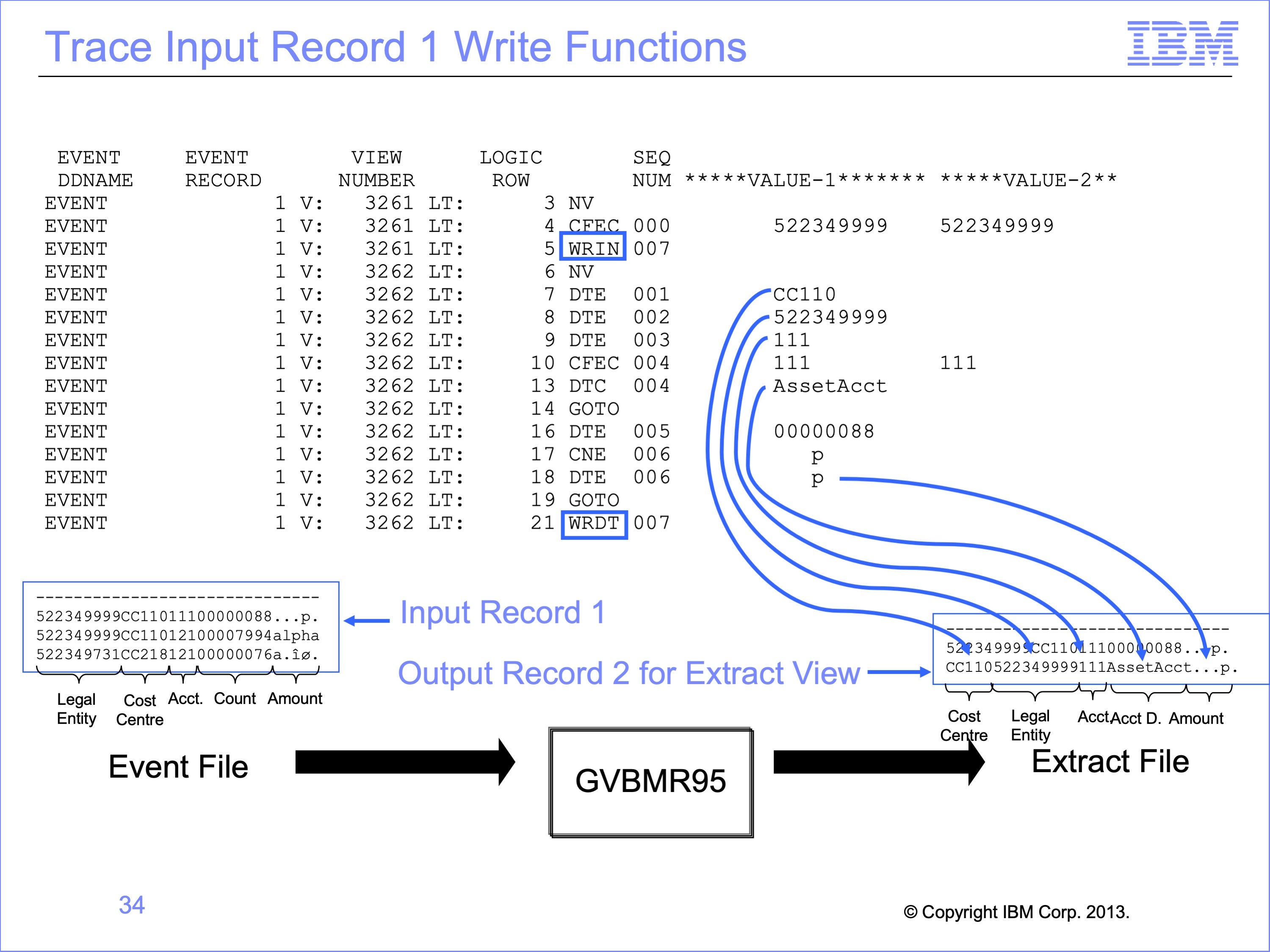
The Single Pass architecture allowed the same record to be used to create two output records, one which was an identical copy, and one which contained selected fields and constants. The second record in the output file contains many of the same fields as the input, but in a different order, for the Cost Center and Legal Entity, each built by DTE functions.
The Account value of “111” is written to the same position as in the input record by a DTE function
The Account Description is next, in this case Asset Account, built by a DTC function.
Having tested the amount on the input file and found it to be numeric, the view copies it in the last position to the output file using a DTE function.
Both views are able to make use of the same input record, without having to read the file twice. By making changes to the view, these output records could also have been written to different output files if desired.
Slide 35
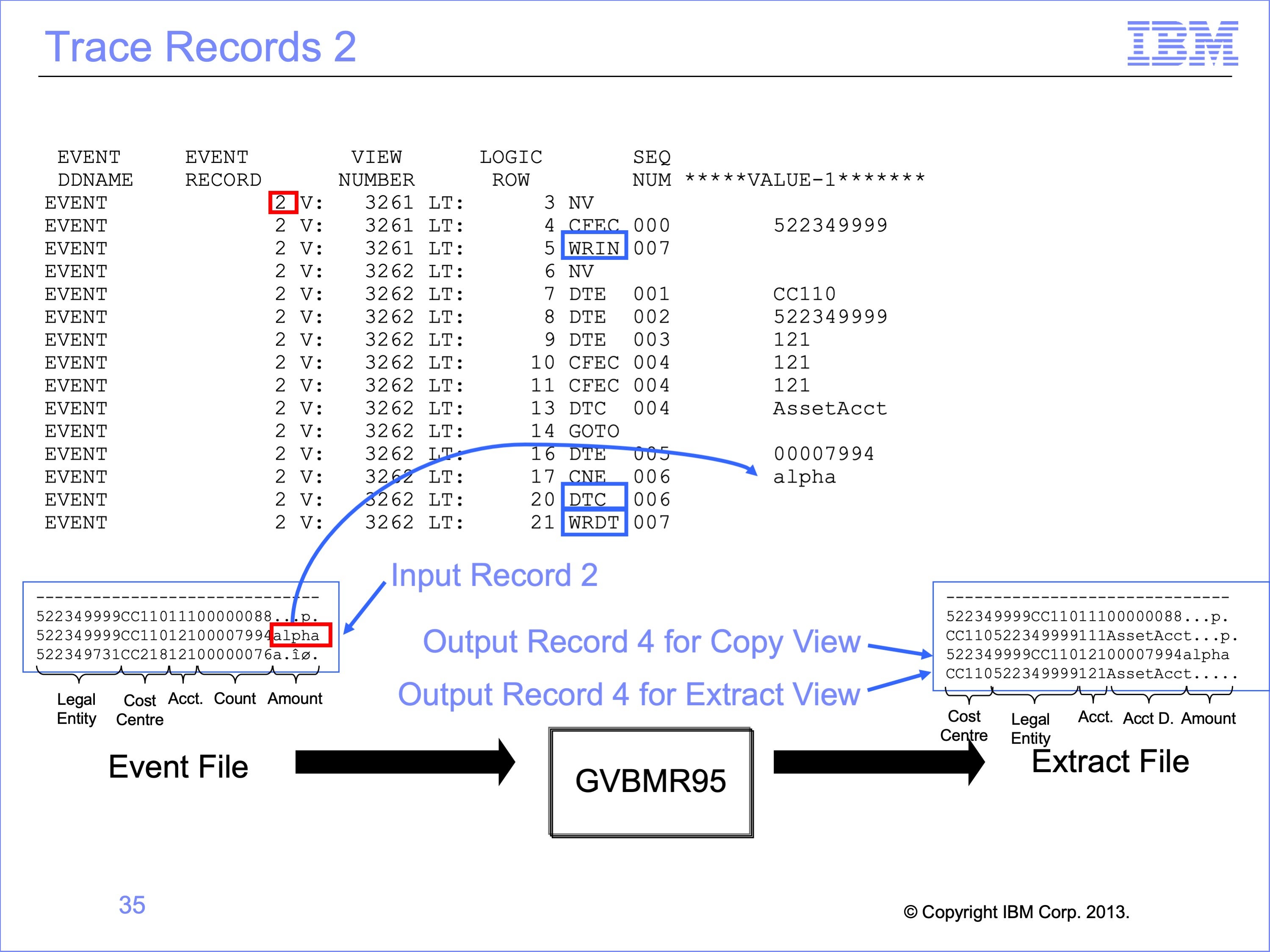
Record 2 follows a similar pattern. Record 2 is passed first to the Copy view which writes it to the extract file. Record 2 is then passed to the Extract Only View.
Note that the AMOUNT field on the input record two has a non-numeric amount of “alpha” in it. This causes the Extract Only CNE test to be false, and thus this value is not moved to the output record. Rather a packed constant of zero is moved to the output file (which is unprintable in this slide and shown as a series of periods).
Slide 36
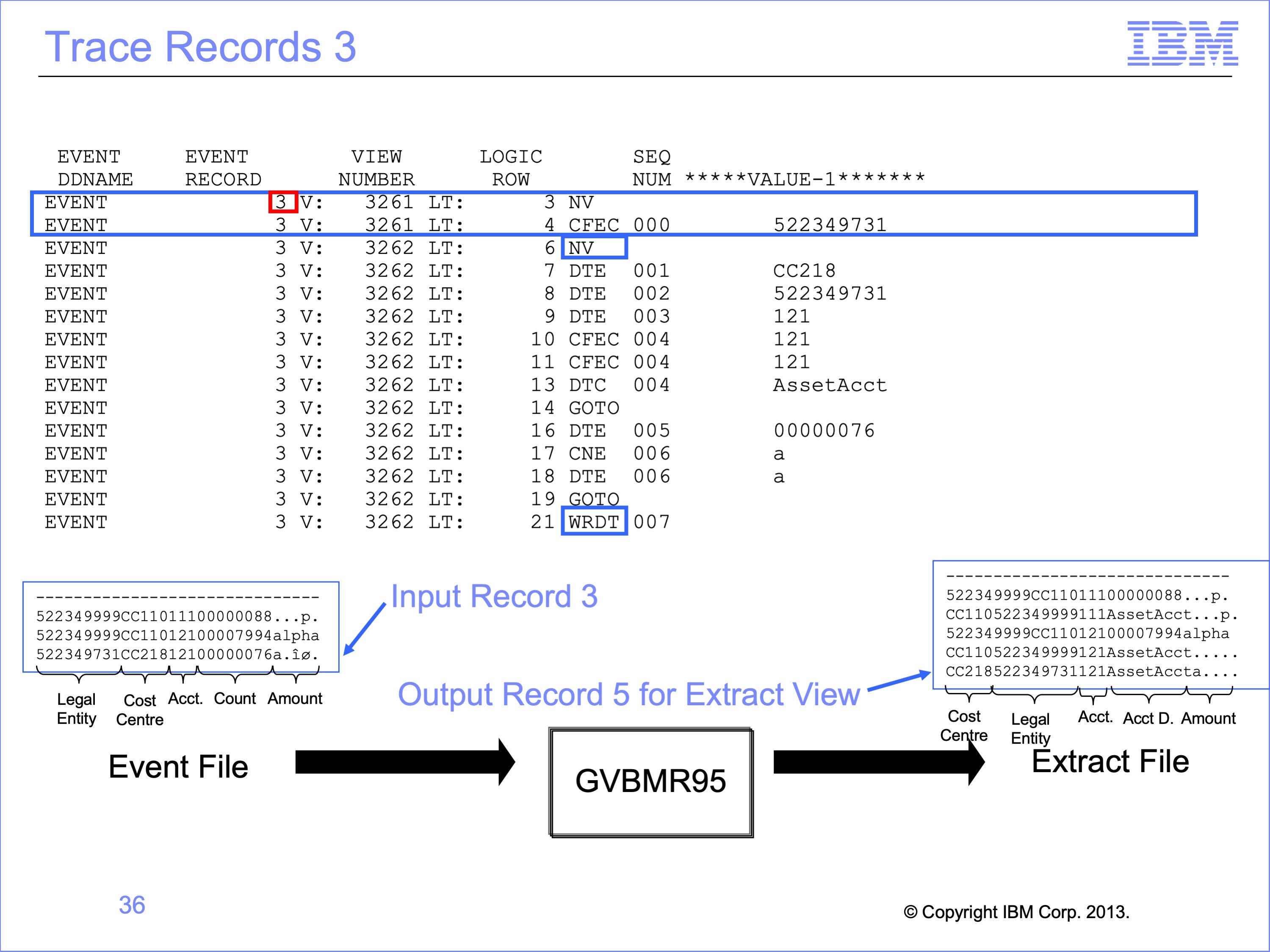
Record 3 is read, which then is NOT selected by the Copy Only view because the Legal Entity tests false; the Legal Entity is 731, not the 999 required. Thus this record is not written to the extract file, and the input records is passed to the Extract Only view.
When record 3 is processed by the Extract Only view, it is written to the output file.
Slide 37
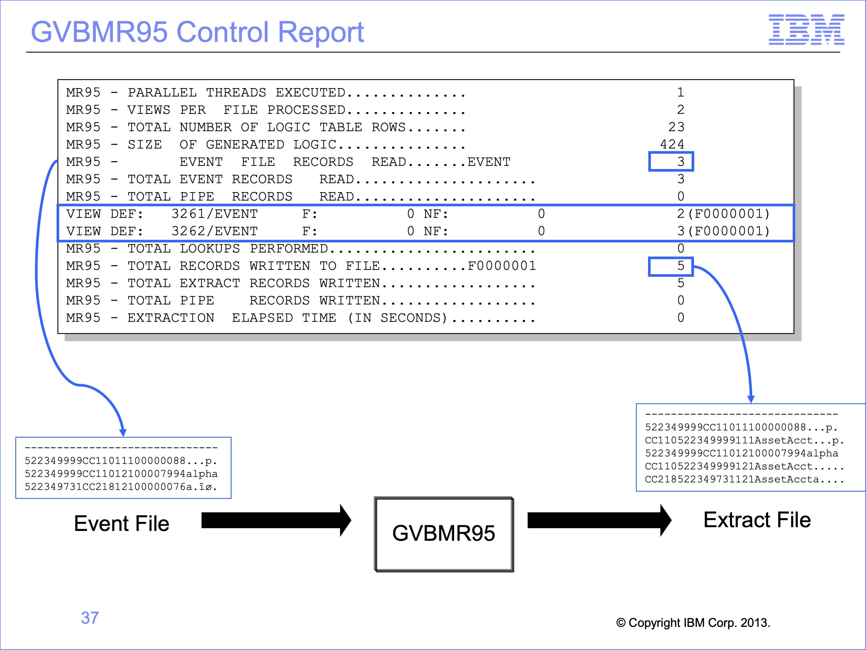
The GVBMR95 Control Report shows that the three records in the input file have become 5 records in the output files: 2 for the Copy Only view, and 3 for the Extract Only view.
The Extract Engine in this process has significantly increased efficiency over alternative methods of producing these two outputs, because in a single pass of the file, one IO to get the event file into memory for processing has allowed both outputs to be done. Certainly programs can be written to do this same thing, but it demands a programmer writing the program to design it that way. With SAFR, two people independently can create views, and the tool will resolve them efficiently.
Remember, though, that this process does not include any parallelism. View number 2 is executed after view number 1 has seen the event record. We’ll explain parallelism in a later module.
Slide 38
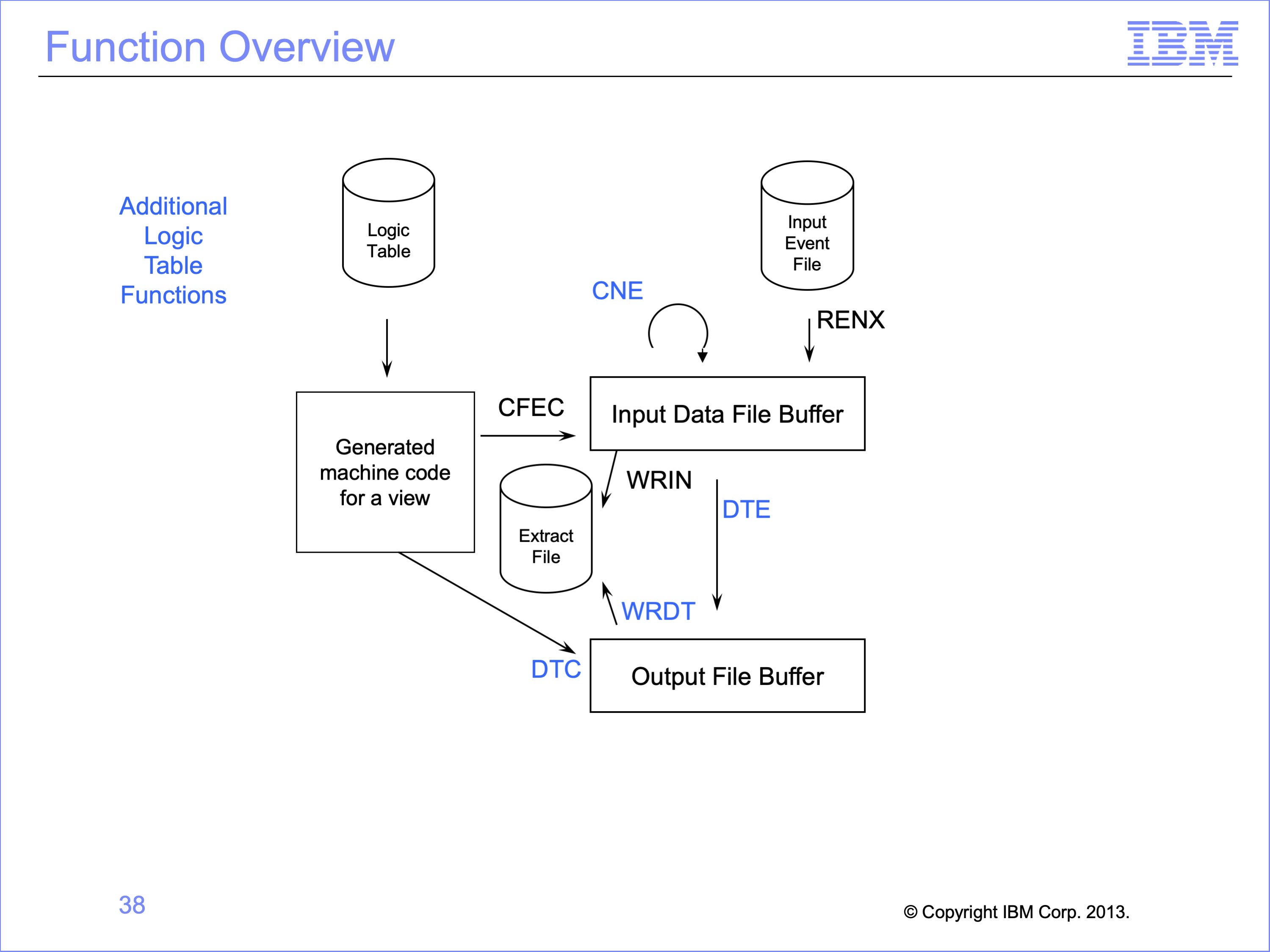
This logic table and module has introduced the following Logic Table Function Code:
- CNE, a Class test Numeric on an event file field.
- DTE, which moves an input field to the output buffer
- DTC, which moves a constant from the logic table to the output buffer
- WRDT, which writes the DT data to the extract file
Slide 39
This module described the single pass architecture and additional logic table processing using the Extract Only view. Now that you have completed this module, you should be able to:
- Describe the Single Pass Architecture
- Read an Extract only Logic Table and Trace
- Explain the Function Codes used in the example
- Debug AND and OR selection logic
Slide 40
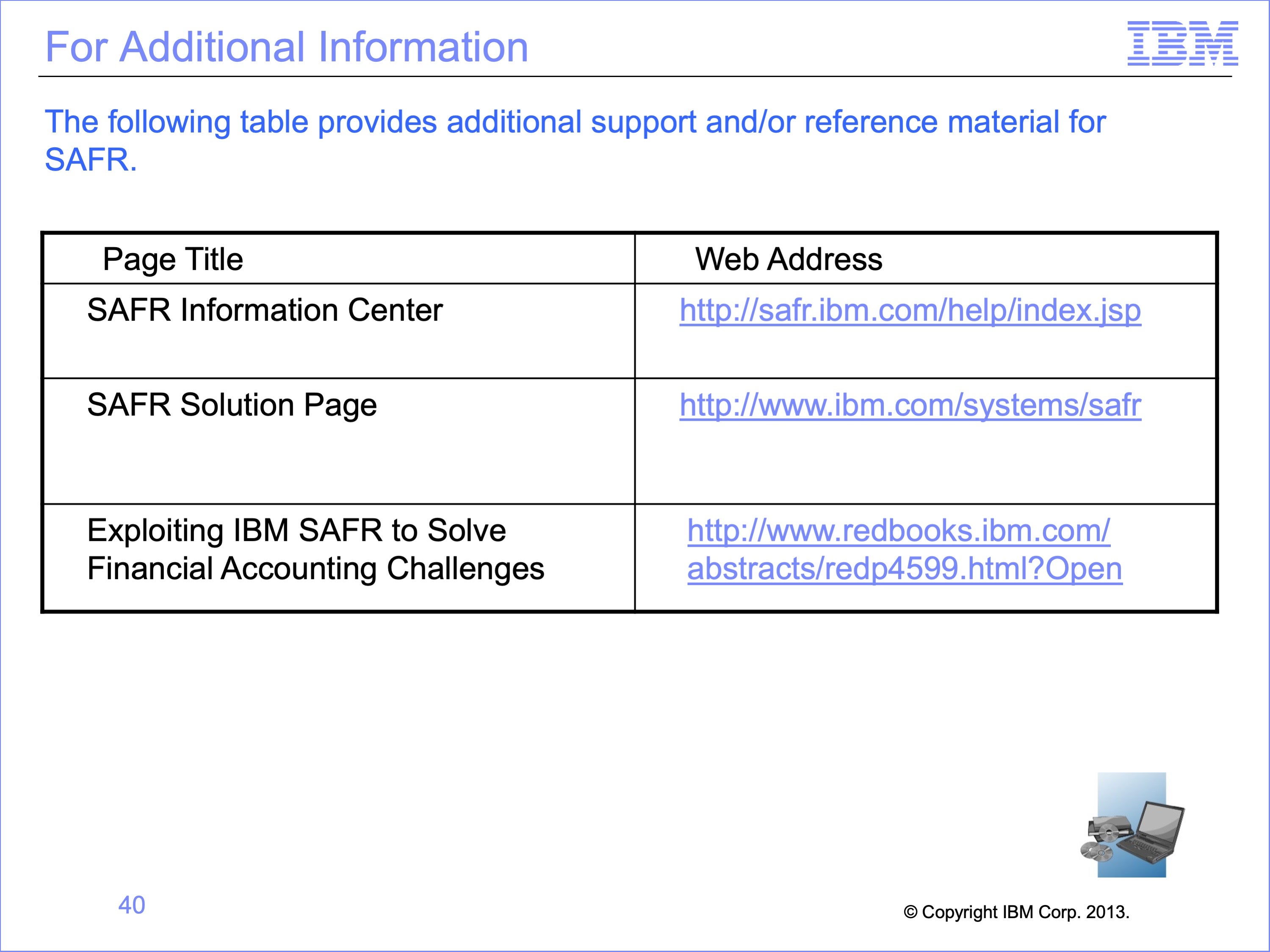
Additional information about SAFR is available at the web addresses shown here. This concludes Module 12, The Single Pass Architecture
Slide 41